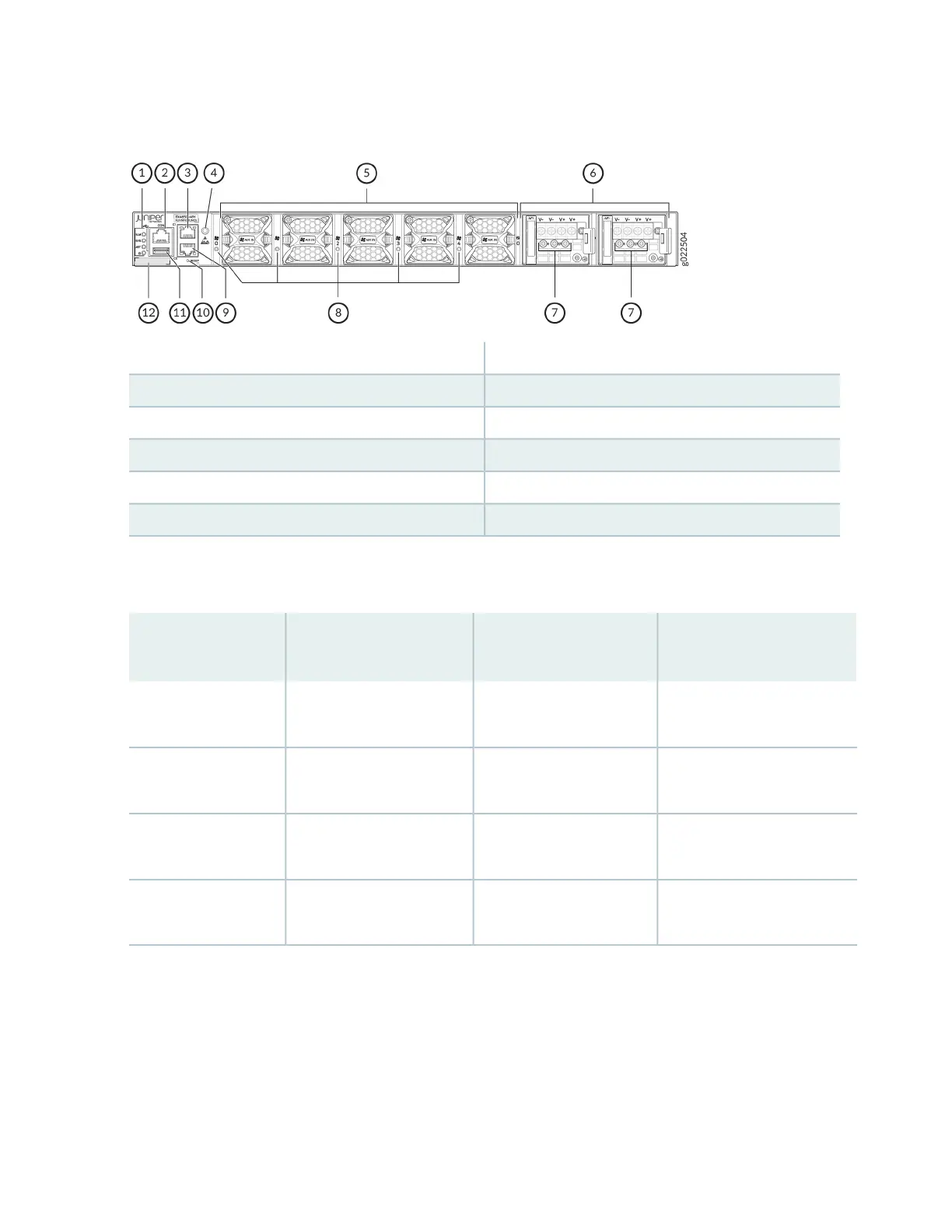
Figure 6: Components on the Rear Panel of a DC-Powered EX4650 Switch
7—1— Power supply LEDsChassis status LEDs (ALM, SYS, MST, ID)
8—2— Fan module LEDsConsole port
9—3— RJ-45 management port (C0)RJ-45 management port (C1)
10—4— RESET buttonESD point
11—5— USB portFan module
12—6— CLEI labelPower supplies
Table 3 on page 23 lists the EX4650 switch models and their components.
Table 3: Components in EX4650 Switches
Power Supply Shipped by
Default
Fan Modules Shipped by
DefaultBuilt-in PortsSwitch Model
Two 650 W AC power
supplies (1+1 redundancy)
Five fan modules; each with
an AFO label
48x25G SFP28 ports and
8x100G QSFP28 ports
EX4650-48Y-AFO
Two 650 W AC power
supplies (1+1 redundancy)
Five fan modules; each with
an AFI label
48x25G SFP28 ports and
8x100G QSFP28 ports
EX4650-48Y-AFI
Two 650 W DC power
supplies (1+1 redundancy)
Five fan modules; each with
an AFO label
48x25G SFP28 ports and
8x100G QSFP28 ports
EX4650-48Y-DC-AFO
Two 650 W DC power
supplies (1+1 redundancy)
Five fan modules; each with
an AFI label
48x25G SFP28 ports and
8x100G QSFP28 ports
EX4650-48Y-DC-AFI
Power Supplies
Each EX4650 switch supports two AC or two DC power supplies with either front-to-back or back-to-front
airflow. Power supplies for the EX4650 switch are fully redundant, load-sharing, and hot-removable and
hot-insertable field-replaceable units (FRUs). The EX4650 switch models are shipped with two power
supplies preinstalled in the rear panel of the chassis.
23
 Loading...


