•
Front-to-back (air exhausts through the back of the switch), indicated by the label AIR OUT (AFO)
CAUTION: Do not mix AFI and AFO fans and power supplies in the same chassis.
Fan Modules
The fan modules in EX4650 switches are hot-insertable and hot-removable FRUs. These fan modules are
designed for one of the two available airflow directions (Airflow In or Airflow Out). The fan modules are
also color-coded to indicate the airflow direction. The fan modules are installed in the fan module slots
between the management panel and the power supplies.
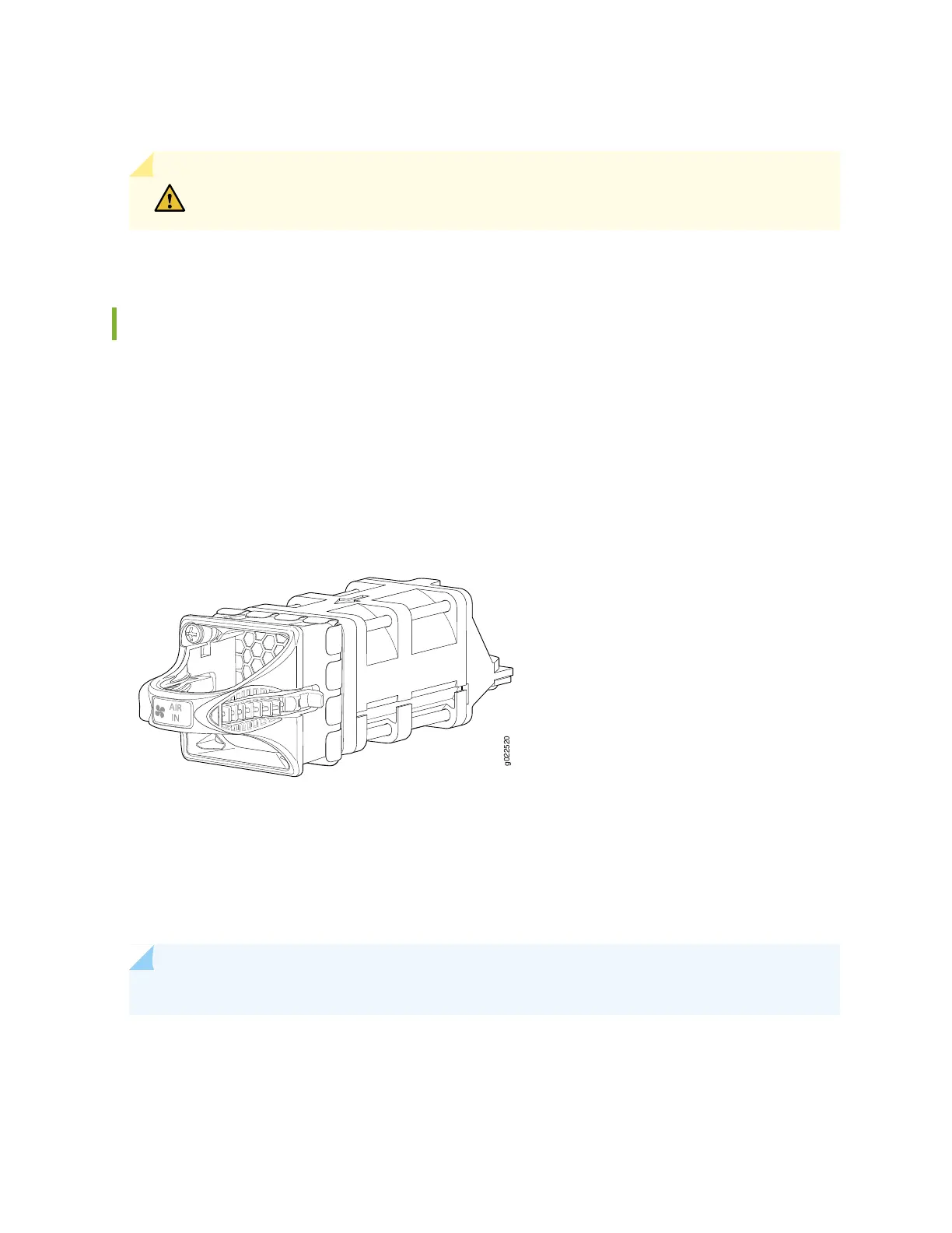
Figure 13 on page 34 shows the EX4650 fan module.
Figure 13: EX4650 Fan Module
The five fan modules are numbered 0 through 4 counting from left to right. Each fan module slot has a
fan icon and an LED next to it.
You must remove only one fan module at a time for replacement from the rear panel of the chassis. The
switch continues to operate for a limited period of time (30 seconds) during the replacement of the fan
module without thermal shutdown.
NOTE: All the five fan modules must be installed for optimal functioning of the switch.
The fan modules are available in four models that have different airflow directions—back-to-front (air
enters through the back of the switch), indicated by the label AFI and azure blue color, and front-to-back
34
 Loading...


