10. Switch on the external circuit breakers to provide voltage to the DC power source
cable leads.
NOTE: Each PDM must be connected to a dedicated 60 A or 80 A DC
circuit breaker for the DC power source. The PDM has a switch to
accommodate DC circuit breaker amperage.
11. Verify that the power cabling is correct, that the cables are not touching, and that they
do not block access to router components or drape where people could trip on them.
12. Close the cable restraint cover over the terminal studs, and tighten the captive screws.
Connect DC Power Supply Modules
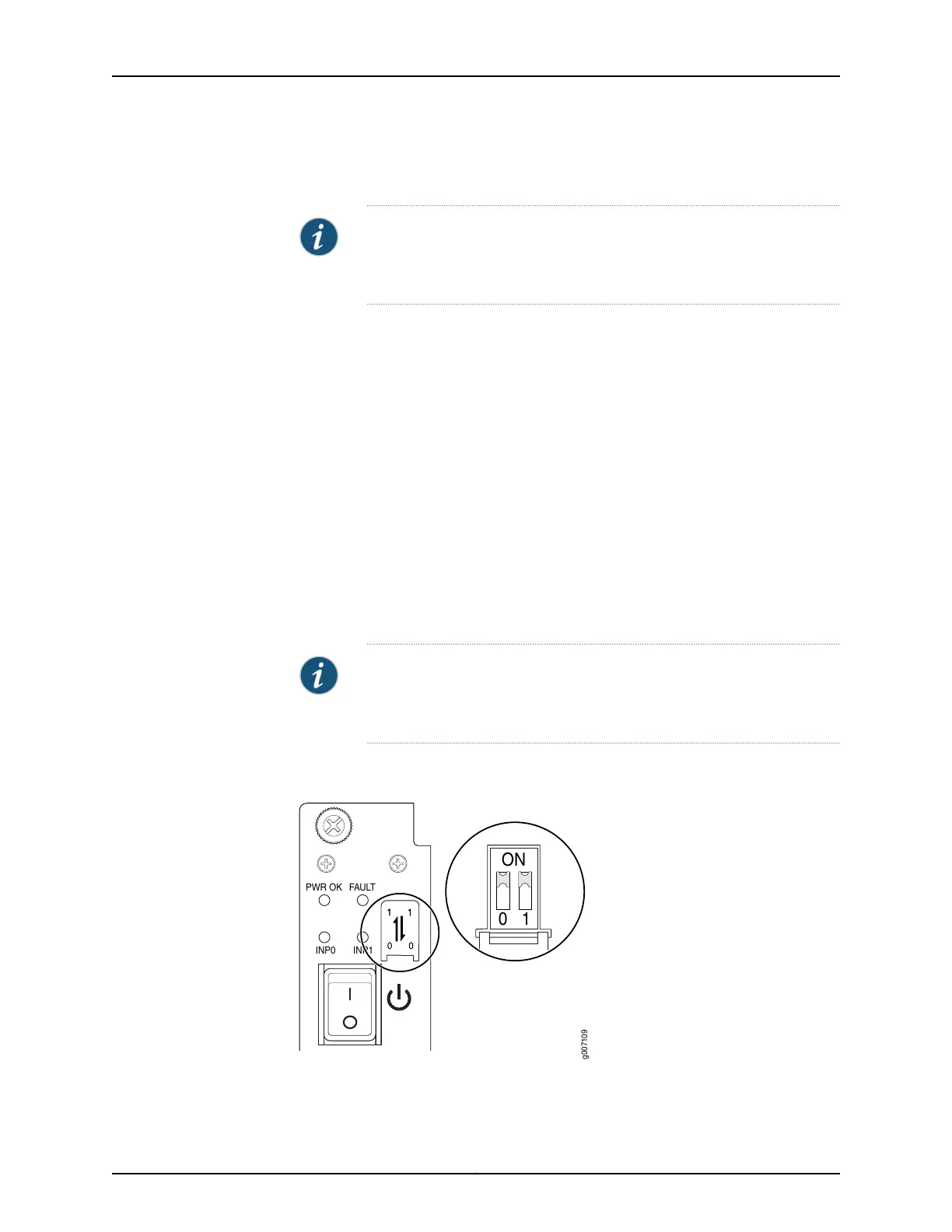
1. Verify that the power switches on the PSM is in the off (O) position (see
Figure 41 on page 60).
2. On the PSM, slide the plastic cover away from the input mode switch to expose the
dual DIP switches. Move the input mode DIP switch 0 (left switch) to the ON position
for the bottom feed INP0 (expected to be connected), and DIP switch 1 (right switch)
to the ON position for the top feed INP1 (expected to be connected). If both DIP
switches 0 and 1 are turned to the ON position, then both top and bottom feeds are
expected to be connected (see Figure 41 on page 60).
In addition, a PSM failure triggers the alarm LED on the craft interface.
NOTE: The DIP switches are used only to indicate presence of a feed. If
both feeds are present, power is always drawn from feed 0. Only if feed
0 fails will power be drawn from feed 1.
Figure 41: Selecting DC Power Subsystem Feed Redundancy
PWR OK
FAULT
INP0
INP1
10
ON
g007109
Copyright © 2015, Juniper Networks, Inc.60
MX2020 3D Universal Edge Router Quick Start

 Loading...