Electrical connection
Page Operating Instructions for Powador .-. TL_EN
ENEN
Authorised electrician
. Cable and fuse requirements
Make the connection to the PV generator as well as the grid connection via the PCB terminals in the connection area
of the inverter. Note the following cable cross-sections:
AC connection (M/XL/F) DC connection (M) DC connection (XL/F)
Max. conductor cross-sec-
tion without wire sleeves
50 mm² 35 mm² 10 mm²
Max. conductor cross-sec-
tion with wire sleeves
30.0-48.0 TL3: 50 mm²
60.0-72.0 TL3: 35 mm²
35 mm² 10 mm²
Length of insulation to be
stripped o
dependent on the utilised terminal type
Tightening torque 30.0-48.0 TL3: 4-4,5 Nm
60.0-72.0 TL3: 2.5-4 Nm
- 2.5 Nm
Table 4: Recommended conductor cross-section
Version M Version XL Version XL SPD 1+2
String fuses To be provided externally on-site internal, fuse size depends on connection
Overvoltage conductors
(surge protection device)
To be provided externally on-site Installed internally, Type II,
1 per MPP tracker
Installed internally, Type
I+II, 1 per MPP tracker
Combiner box To be provided externally on-site Installed internally
Parallel connection of
the DC inputs
Parallel connection not possible,
connection via individual cables
Parallel connection not possible, connection via
individual cables
Overvoltage safety class DC: III, AC: III DC: II + III, AC: III
Overvoltage category DC: II, AC: III DC: II, AC: III
DC connection terminals 3 (1 per MPP tracker) 30.0-60.0 TL3: 12 (4 per MPP tracker)
72.0 TL3: 15 (5 per MPP tracker)
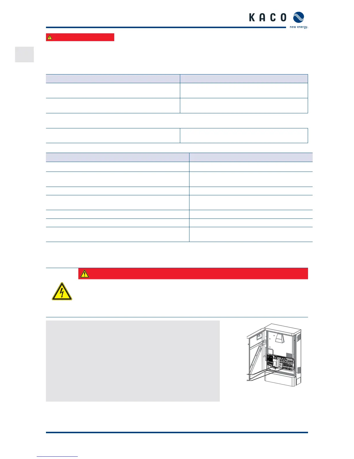
. Connection to the power grid
The power connection wires are connected to the AC terminal on the left of the connection area (see Figure ).
DANGER
Danger to life from electric shock!
Severe injury or death will result if the live connections are touched.
› Switch o all power sources to the inverter before you insert the grid power cable into the unit.
› Isolate before carrying out work on the public power supply and the system power supply.
Prepare the grid connection
ඣ Use core cable (L brown, L black, L grey, N blue, PE green/yellow)
or core cable (L brown, L black, L grey, PE green/yellow).
. Loosen cable tting for AC connection.
. Remove the outer cladding of the AC cables.
. Insert the AC cables through the cable tting into the connection area.
. Strip the insulation from the AC cables.
. Making the grid connection.
AC-Side
DC-Side
Figure : Connection terminals
 Loading...