Description
Operating Instructions for Powador .-. TL_EN Page
EN
Description
. Mode of Operation
The inverter converts the DC voltage generated by the PV modules into AC voltage and feeds it into the grid. The
starting procedure begins when there is sucient sunlight and a specic minimum voltage is present in the inverter.
The feed-in process begins once the PV generator has passed the insulation test and the grid parameters are within
the requirements imposed by the grid operator for a specic monitoring time. If, as it gets dark, the voltage drops
below the minimum voltage value, feed-in operation ends and the inverter switches o.
. Diagram
1
2
3
4
5
6
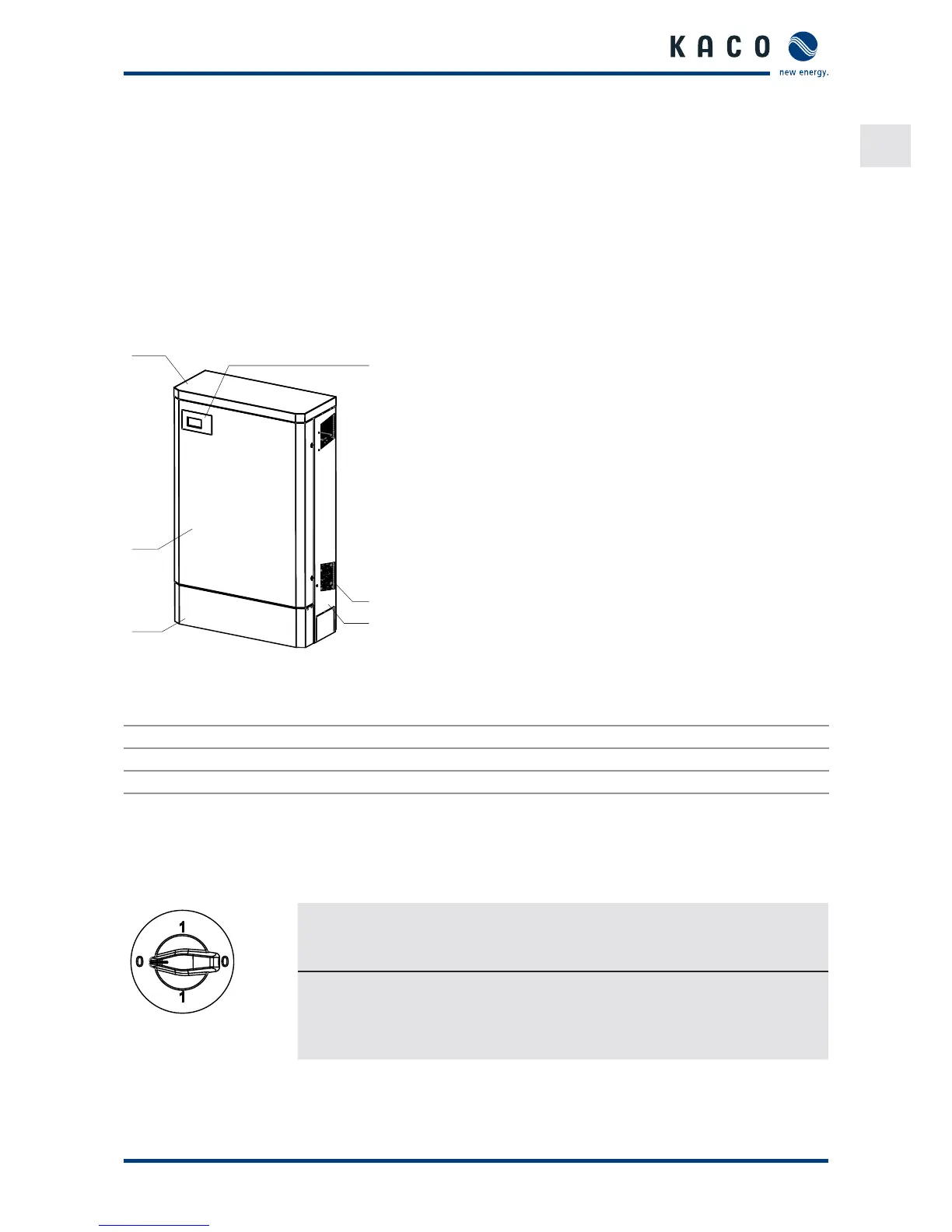
Figure : Inverter diagram
Key
1 Upper housing cover 4 Control panel
2 Doors 5 Fan cover
3 Cover for the connection area 6 Side housing cover
.. Mechanical components
DC isolator switch
There are DC isolator switches inside the inverter housing. The DC isolator switch is used to disconnect the inverter
from the PV generator in order to carry out service activities.
Figure : DC isolator
switch
Disconnecting the inverter from the PV generator
" Switch the DC isolator switches from (ON) to (OFF).
Connecting the inverter to the PV generator
" Switch the DC isolator switches from (OFF) to (ON).
.. Electrical functions
A potential-free relay contact is integrated in the inverter. Use this contact for one of the following functions:
 Loading...