Electrical connection
Operating Instructions for Powador .-. TL_EN Page
EN
Authorised electrician
1
2
3a
3b
1
2
3a
4
3c
1
2
3a
4
3b
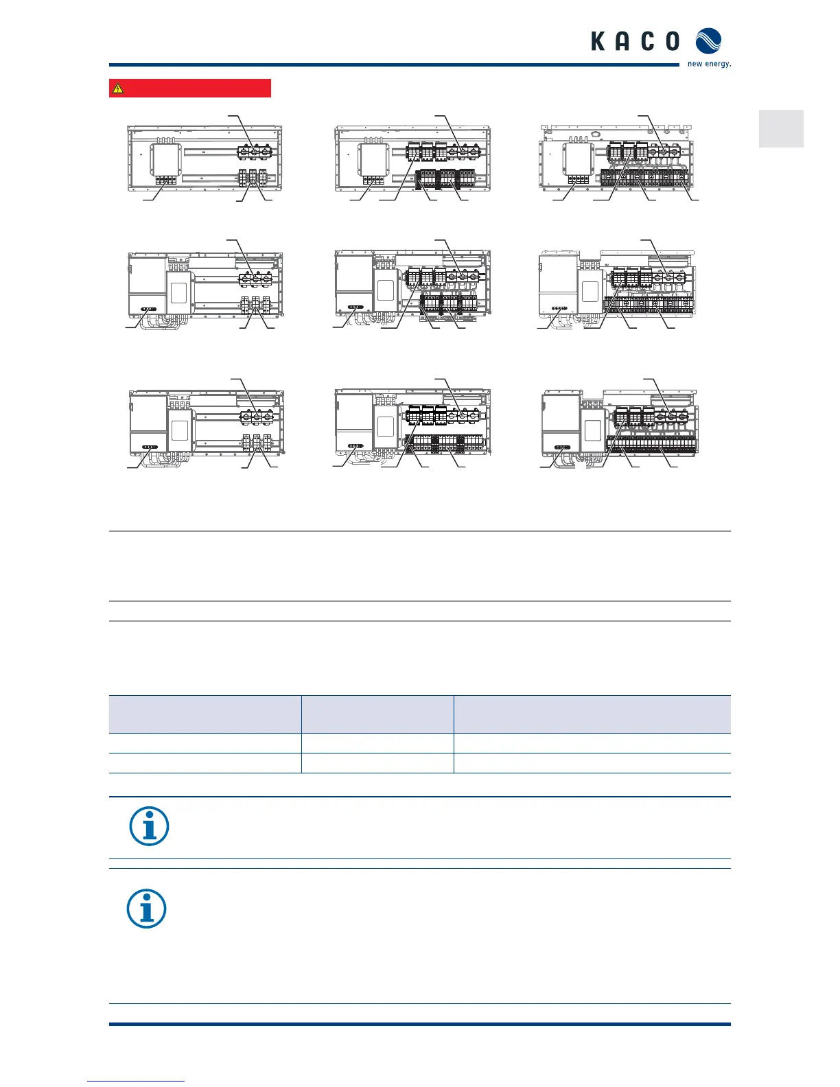
Figure : Powador .-. TL - M Figure : Powador .-. TL - XL* Figure : Powador .-. TL - XL- F*
2
3a
3b1
2
3a
4
3c
1
2
3a
4
3b
1
Figure : Powador . TL - M Figure : Powador . TL - XL* Figure : Powador . TL - XL - F*
2
3a3b
1
2
3a
4
3c
1
2
3a
4
3b
1
Figure : Powador . TL - M Figure : Powador . TL - XL* Figure : Powador . TL - XL*
Key
1 AC connection terminals 3 DC connection terminals
3a) Fuse block (DC+)
3b) Fuse block (DC-)
3c) Feed-through terminal (DC-)
2 DC isolator switch 4 Overvoltage protection type II (*- SPD 1+2)
Recommended conductor cross-sections and fuse protection of NYM cables for xed wiring according to VDE
part
For cable lengths up to m, use the named conductor cross-sections. Longer cable lengths require larger conduc-
tor cross-sections.
Equipment types Conductor cross-sec-
tion
Fuse protection: gL safety fuses
Powador 30.0 - 48.0 TL3 M/XL/F 16 mm² 63 A for 16 mm² conductor cross-section
Powador 60.0 - 72.0 TL3 M/XL/F 35 mm² 100 A for 35 mm² conductor cross-section
Table 5: Recommended conductor cross-sections and fuse protection of NYM cables
NOTE
When selecting installation material, please consider the suitability of the product to the mains
voltage (.-. TL, . TL: / V. . TL, . TL: / V).
NOTE
An AC-side disconnection unit must be provided during the nal installation stage. This cut-o
mechanism must be installed so that it can be accessed at any time without obstruction.
If a residual current circuit breaker is necessary due to the installation specication, a type A residual
current circuit breaker must be used.
For questions regarding the appropriate type, please contact the installer or our KACO new energy
customer service.
 Loading...