Electrical connection
Page Operating Instructions for Powador .-. TL_EN
ENEN
Authorised electrician
NOTE
If the cable impedance is high (i.e. long grid-side cables), the voltage at the grid terminals of the
inverter will increase during feed-in to the grid. The inverter monitors this voltage. If it exceeds the
country-specic grid overvoltage limit value, the inverter switches o.
› Ensure that the conductor cross-sections are suciently large or that the cable lengths are su-
ciently short.
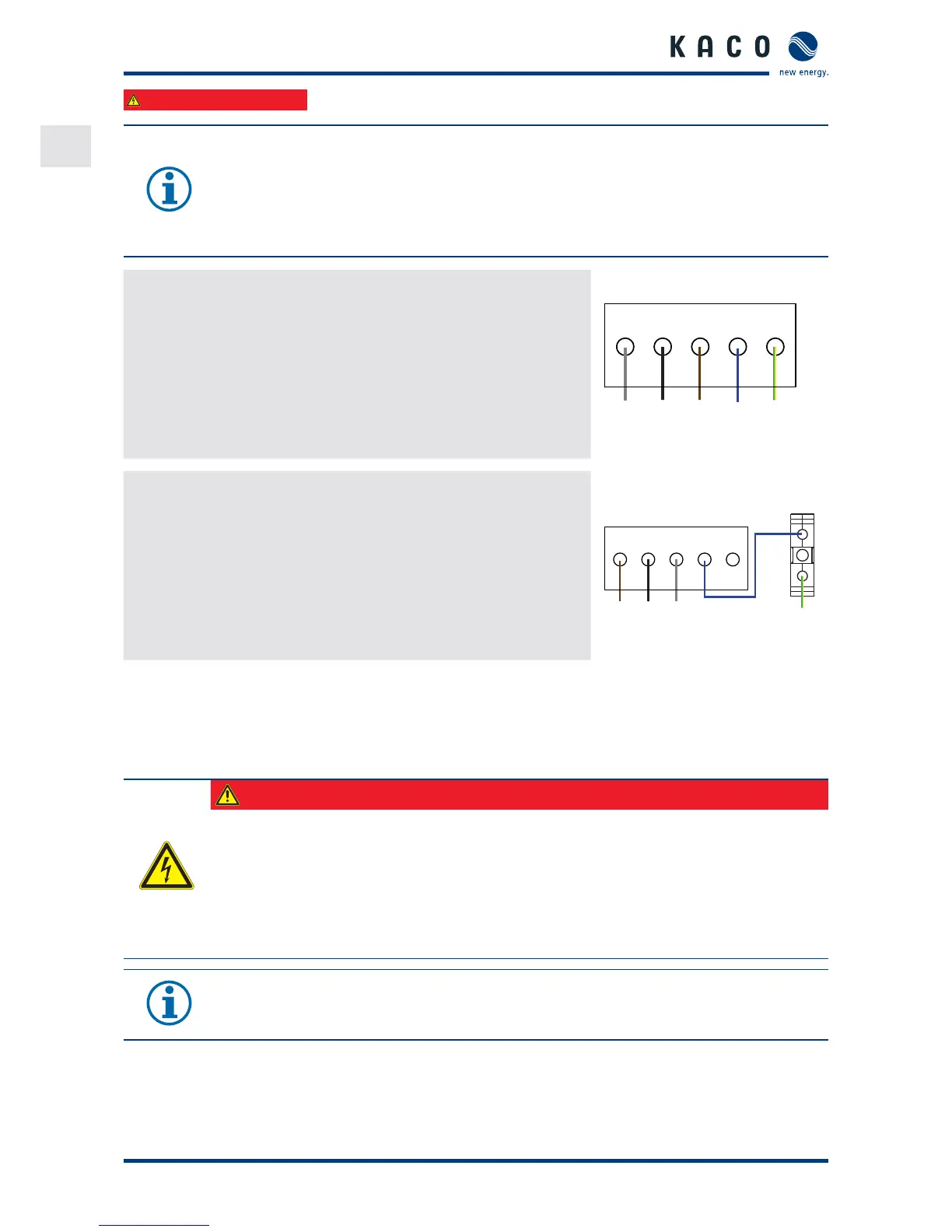
Making the grid connection ( core connection, TN-S system)
. Run L, L, L, N through the included ferrite (. TL only).
. Connect the cables in accordance with the label on the PCB terminals
(Figure on page ).
. Connect terminal "PE" to the equipotential bonding of your lightning
protection system using a mm² wire.
. Check secure t of all connected cables.
. Tighten the cable tting.
PE
N
BU
L2
BK
L1
BN
GNYE
L3
GY
» The inverter is now connected to the power grid. Figure : -pole connection
Making the grid connection ( core connection, TN-S system)
. Fit the PE terminal (not supplied) to the hat rail. Note the cable
cross-sections.
. L, L, L through the included ferrite (. TL only).
. Connect the cables in accordance with the label on the PCB terminals
(Figure on page ).
. Check secure t of all connected cables.
. Tighten the cable tting.
L1 L2 N PE
PEN
L3
L1 L2 L3
» The inverter is now connected to the power grid. Figure : -pole connection
* Connect the overvoltage conductor with only one PE terminal.
.. Connecting the PV generator
Connect the PV generator on the right of the connection area (see Figure on page ).
Use the provided cable ttings.
DANGER
Risk of fatal injury due to contact voltages.
› During installation: Electrically disconnect the DC positive and DC negative from the protective
earth (PE).
Removing the plug connection before disconnecting the inverter from the PV generator may lead to
injuries and damage the inverter.
› Disconnect the inverter from the PV generator using the integrated DC isolator switch.
› Remove the plug connector.
NOTE
Connected PV modules must be dimensioned for the DC system voltage in accordance with IEC
Class A, but at least for the value of the AC grid voltage
 Loading...