Configuration and Operation
Page Operating Instructions for Powador .-. TL_EN
ENEN
Conguration and Operation
. Controls
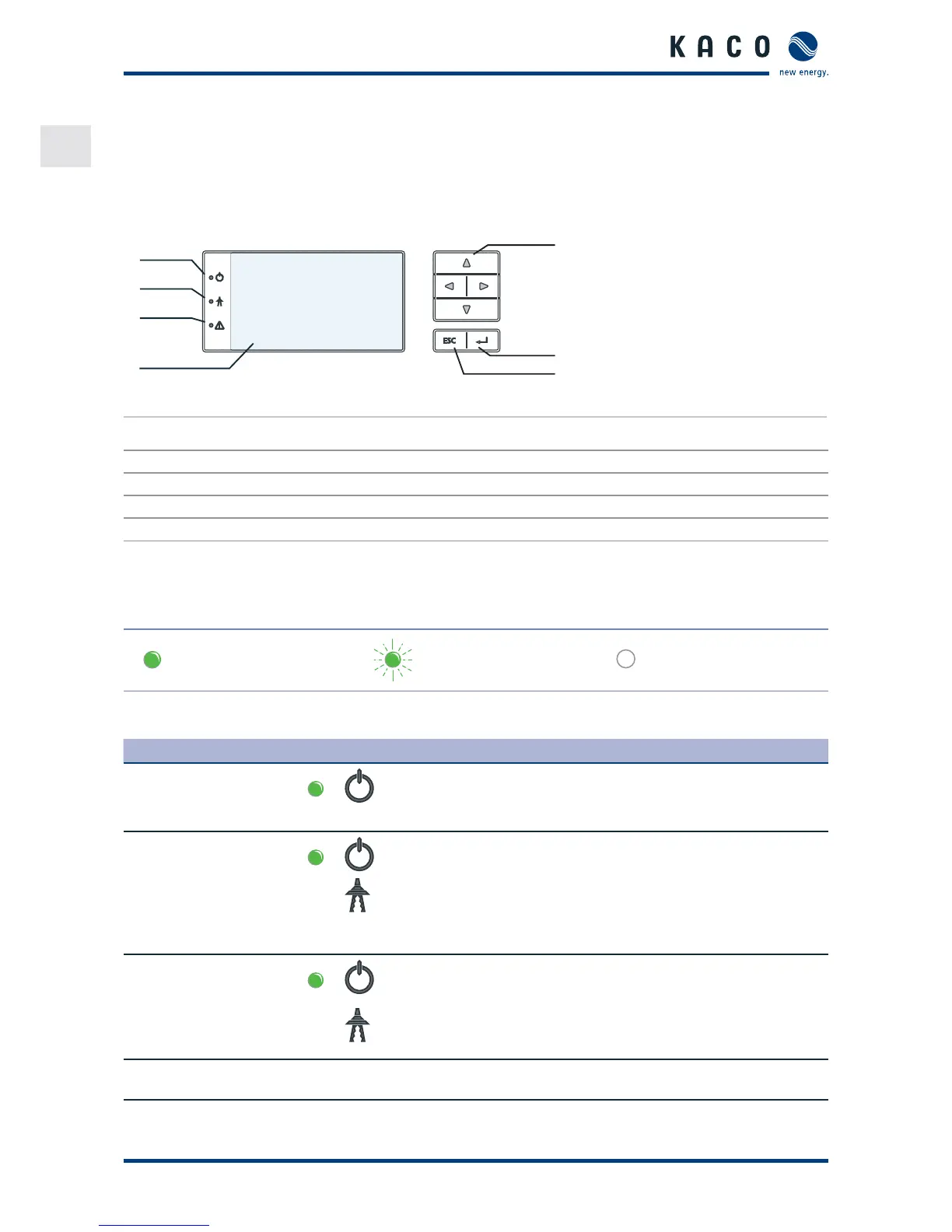
The inverter has a backlit LCD as well as three status LEDs. The inverter is operated using six buttons.
1
2
3
4
5
6
7
Figure : Control panel
Key
1 "Operating" LED 5 4-way button
2 "Feed-in" LED 6 “Enter” key
3 "Fault" LED 7 “ESC” key
4LCD
.. LED indicators
The LEDs on the front of the inverter show the dierent operating states.
The LEDs can display the following states:
LED illuminated LED ashing LED not illuminated
The LED indicators show the following operating status:
Operating status LEDs Display Description
Start The green "Operating" LED is illuminated
if an AC voltage is present,
(independently of the DC voltage).
Feed-in start
Power fed into the grid
or measured values
The green "Operating" LED is lit.
The green "Feed-in" LED is illuminated
after the country-specic waiting period*.
The unit is ready to feed in, i.e. is on the
grid.
You can hear the grid relay switch on.
Feed-in operation
Power fed into the grid
or measured values
The green "Operating" LED is lit.
The green “Feed-in” LED is illuminated.
The “Feed-in” icon appears on the LC
display.
The unit feeds into the grid.
* The waiting period ensures that all network parameters are in the permissible ranges.
 Loading...