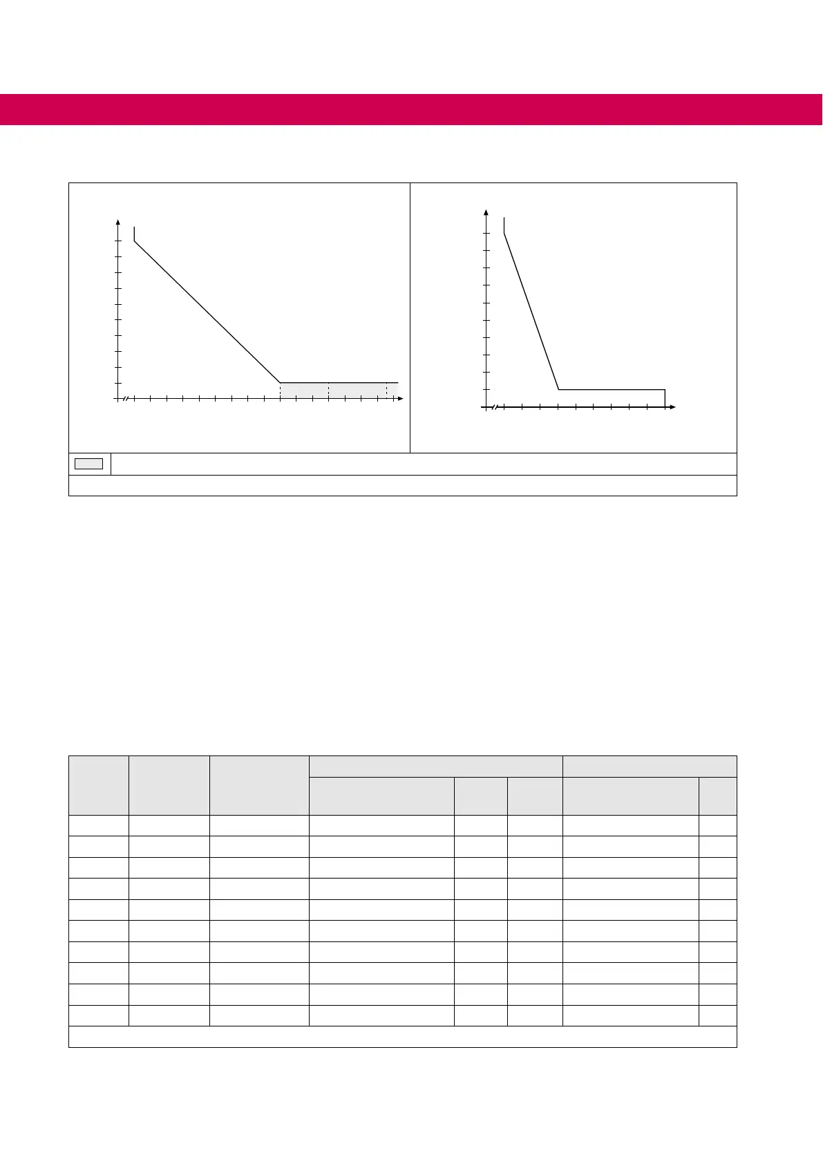
4.1 Overload characteristic
Characteristic 1 Characteristic 2
Time in s
30
60
90
120
150
180
210
240
270
300
0 105 110 115 120 125 130 135 140 145 150 160 170 180 190 200
210 220
Time in s
30
60
90
120
150
180
210
240
270
300
0 105 110 115 120 125 130 135 140 145 150
Load in % Load in %
The characteristic declines device-dependently in this range.
Figure 1: Overload characteristic
On exceeding a load of 105% the overload integrator starts. When falling below the
integrator counts backwards. If the integrator achieves the overload characteristic that
corresponds to the drive converter, the error E.OL is triggered.
4.2 Accessories
4.2.1 AIC, LCL and EMC lters
Theline-sideAICorLCLltersarerequiredforthecharacteristicofsinusoidalcurrents.
Theyltertheswitchingfrequencyofthedriveconverter.Thebasicassemblyconsists
oftwoinductorsandcapacitors(LCLlter).AnEMClterisadditionallyintegratedatthe
AIClters.
Size Housing Cooling
AIC / LCL lters EMC lter
Material number
f
SN
kHz
IN
A
Material number
IN
A
14 E Air 14H6J4E-1000 8 16.5 integrated –
16 G Air 19H6J4E-1000 8 36 integrated –
18 H Air 19H6J4F-1000 8 60 integrated –
20
1)
R Air 19H6J4F-1000 8 60 integrated –
20 R Air 21H6J4F-1001 8 90 integrated –
22
1)
R Air/water 24H6J4F-1000 8 108 integrated –
24 U Air/water 24H6J4G-1000 8 180 integrated –
26 U Air/water 26Z1K04-1000 4-16 250 26E4T60-1001 300
27
1)
U Water 26Z1K04-1000 8-16 275 26E4T60-1001 300
29 P Water 29Z1K04-A000 4 460 30U5A0W-3000 650
Table 8: AIC, LCL and EMC lters
1)
LCL lter limits the AIC current.
30
UNIT DATA
 Loading...
