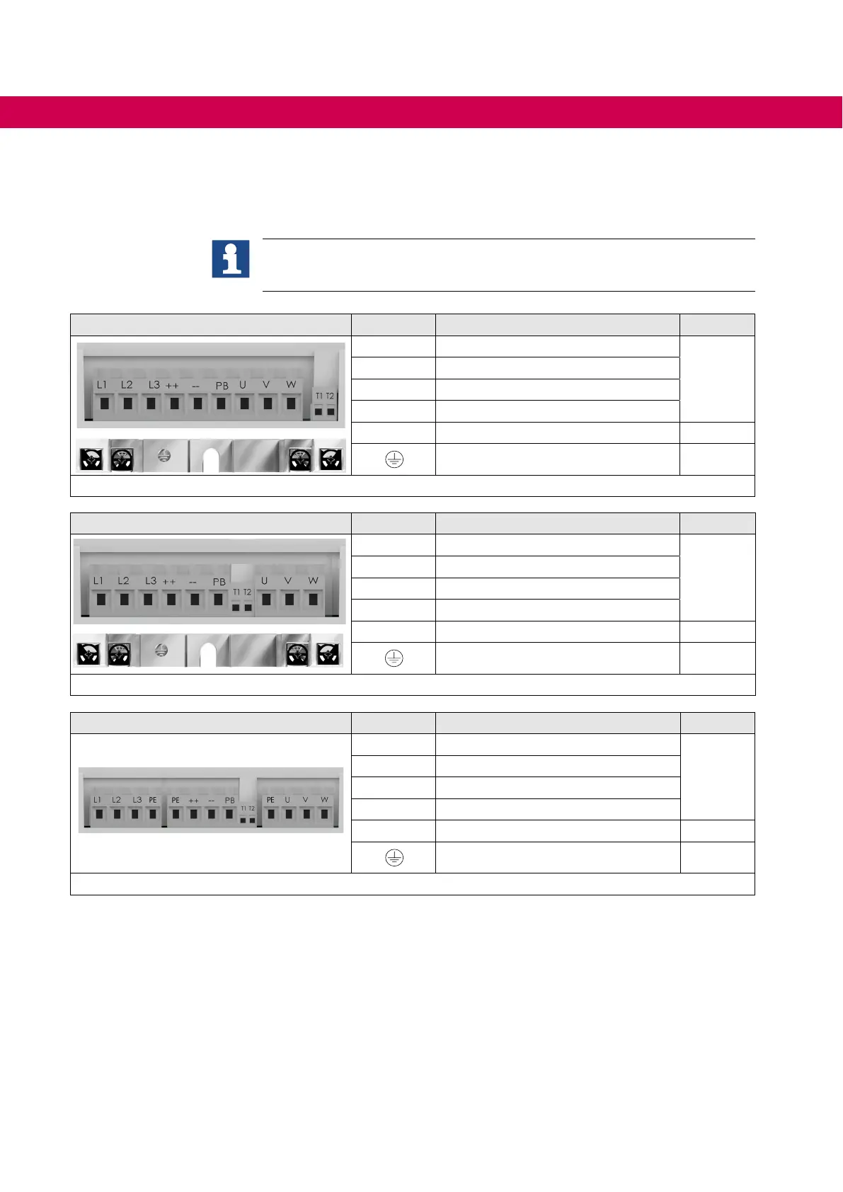
6.2 Terminal blocks of the devices
The assignment of the numbering under "Terminal" for cross sections and tightening
torques => „Cross-sections and tightening torques of the terminals“.
The + contact of the temperature evaluation must be connected to terminal T1
to terminal block X1A! For more information
=> „Temperature detection T1, T2“.
Housing E Name Function Terminal
L1, L2, L3 3-phase mains connection
1
U, V, W AIC mains connection
++, PB Connection for braking resistor
++, – – Connection for DC-bus connection
T1, T2 Connection for temperature sensor 2
PE,
Connection for protective earth 3
Figure 2: Terminal blocks housing E
Housing G Name Function Terminal
L1, L2, L3 3-phase mains connection
4
U, V, W AIC mains connection
++, PB Connection for braking resistor
++, – – Connection for DC-bus connection
T1, T2 Connection for temperature sensor 2
PE,
Connection for protective earth 3
Figure 3: Terminal blocks housing G
Housing H Name Function Terminal
L1, L2, L3 3-phase mains connection
5
U, V, W AIC mains connection
++, PB Connection for braking resistor
++, – – Connection for DC-bus connection
T1, T2 Connection for temperature sensor 6
PE,
Connection for protective earth 5
Figure 4: Terminal blocks housing H
36
CONNECTION OF THE COMBIVERT F5-AIC
 Loading...
