EasyManua.ls Logo

KEB COMBIVERT 19F5 Series User Manual

KEB COMBIVERT 19F5 Series
72 pages
To Next Page IconTo Next Page
To Previous Page IconTo Previous Page
Page #51 background image
7.1.4 Analog inputs
Connect not connected setpoint inputs to the analog ground to avoid setpoint changes !
Analog setpoint setting external Analog setpoint setting internal
X2A
123456789
PE
0...±10 V DC
Ri = 55 k
+
123456789
Figure 16: Analog inputs
7.1.5 Voltage input external power supply
When the power unit is switched o󰀨 the control remains in operation by an external
voltagesupplyofthecontrolboard.Topreventundenedconditionsatexternalpower
supply, generally the supply unit and then the AIC unit should be switched on.
10 11 17 18 19 20
X2A
21 22 23
+
20…30 V ±0 % / 1 A DC smoothed
Figure 17: Voltage input external power supply
7.1.6 Digital outputs
10 18 19 20
X2A
21 22 23
max. 50 mA DC for both outputs
Figure 18: Digital outputs
51
CONNECTION OF THE CONTROL

Table of Contents

Question and Answer IconNeed help?

Do you have a question about the KEB COMBIVERT 19F5 Series and is the answer not in the manual?

KEB COMBIVERT 19F5 Series Specifications

General IconGeneral
SeriesCOMBIVERT 19F5
CategoryInverter
Output Frequency0-400 Hz
Power Range0.75 kW to 630 kW
Input Voltage380-480 V AC
Output Voltage0-480 V AC
Control MethodVector control, V/f control
Protection FeaturesOvercurrent, overvoltage, undervoltage, overtemperature, short circuit
Communication InterfacesCANopen, Profibus, EtherCAT, Modbus
Cooling MethodAir-cooled, liquid-cooled
Ambient Temperature-10 to +50 °C
Relative Humidity5 to 95% (non-condensing)
Enclosure RatingIP20
Storage Temperature-25 to +70 °C

Summary

Preface: Signal Words and Symbols

Signal words and symbols

Explains hazard symbols and signal words used in the manual.

Preface: Laws, Warranty, Support, and Copyright

Laws and guidelines

Information on EC declaration of conformity and CE mark compliance.

Warranty and liability

Details on warranty terms and manufacturer's liability.

Support and Copyright

Information on requesting further assistance and copyright notices.

Standards for Drive Converters/Control Cabinets: Product and Referenced Standards

Product standards

Standards directly applicable to the drive converter for compliance.

Referenced basic standards

Standards that drive converter standards refer to for context.

Standards for Drive Converters/Control Cabinets: Environmental Standards

Environmental standards

Standards for the drive converter's operating environment and installation.

Basic Safety Instructions: General and Handling

Target group definition

Specifies qualified electrical personnel for manual use.

Transport, storage, and proper use

Guidelines for safe handling, storage, and usage.

Basic Safety Instructions: Installation and Electrical Connection

Installation safety precautions

Critical steps and warnings during device installation.

Electrical connection safety

Essential safety measures for electrical wiring and connections.

Basic Safety Instructions: Testing and Operation

EMC-compatible installation

Ensuring electromagnetic compatibility during installation.

Voltage and insulation testing

Procedures for voltage testing and insulation measurement.

Start-up and operation safety

Warnings and precautions for initial start-up and normal operation.

Basic Safety Instructions: Service and Disposal

Maintenance procedures

Recommended maintenance tasks and frequency.

Repair guidelines

Instructions and warnings regarding device repair.

Disposal instructions

Guidelines for the proper disposal of electronic devices.

Product Description: Overview and Application

Product features and requirements

Overview of COMBIVERT F5-AIC capabilities and operational needs.

Active Infeed Controller view

Explanation of input/output terminal interpretation for AIC.

Product Description: Application Details and Risks

Specified application and restrictions

Permitted uses and limitations of the F5-AIC.

Residual risks and unintended use

Potential hazards and prohibited operations.

Product Description: Part Code Identification

Part code structure

Explanation of the coding system for product identification.

Technical Data: Operating Conditions

Operating conditions overview

General conditions for device operation and storage.

Climatic environmental conditions

Specifics on temperature, humidity, and altitude limits.

Technical Data: Environmental and Electrical Conditions

Mechanical environmental conditions

Vibration and shock limit values for different conditions.

Chemical/mechanical active substances

Contamination limits and environmental interactions.

Electrical operating conditions

Device classification and electromagnetic compatibility (EMC) data.

Unit Data: General and Overload Information

Device size and housing information

Table detailing device sizes, housing types, and cooling modes.

Input and output data

Key electrical parameters for input and output stages.

Unit Data: Filters and Characteristics

Overload characteristic

Graphical representation of overload capabilities and error triggers.

AIC, LCL, and EMC filters

Specific filters required for sinusoidal current characteristics.

Unit Data: Common Mode and EMC Filters

Common mode filter details

Components and function of the common mode filter.

Sinus EMC filters and mains chokes

Alternative filters and chokes for EMC compliance.

Unit Data: DC Fusing Specifications

DC fuses specifications

Table of DC fuses with size, voltage, and current ratings.

Alternative DC-fusing options

Different fuse holder and fuse combinations for DC fusing.

Unit Data: Accessories and Physical Dimensions

Additional precharging resistor

Requirement and specs for precharging resistor in master-slave setup.

Dimensions and weights

Physical characteristics and links to detailed manuals.

Installation: Cabinet Setup and General Instructions

EMC-compatible control cabinet installation

Wiring diagram and components for EMC-compliant cabinet setup.

Installation instructions summary

Key directives for stationary installation and environmental protection.

Connection of the COMBIVERT F5-AIC: Input Terminals and Current Management

Description of input terminals

Table detailing terminal functions for mains and DC voltage inputs.

Current limiting and DC link capacity

Notes on managing current and capacity in DC bus connections.

Connection of the COMBIVERT F5-AIC: Terminal Blocks (Housings E, G, H)

Terminal blocks for Housing E, G, H

Diagrams and assignments for terminal blocks in different housings.

Connection of the COMBIVERT F5-AIC: Terminal Blocks (Housings R, U)

Terminal blocks for Housing R and U

Diagrams and assignments for terminal blocks in R and U housings.

Connection of the COMBIVERT F5-AIC: Terminal Blocks (Housing P)

Terminal blocks for Housing P

Diagrams and assignments for terminal blocks in P housing.

Connection of the COMBIVERT F5-AIC: Terminal Specifications

Cross-sections and tightening torques

Table specifying wire sizes and torque values for terminals.

Connection of the COMBIVERT F5-AIC: Fan Supply

External fan supply for housings P and U

Connection details and power consumption for external fans.

Connection of the COMBIVERT F5-AIC: Temperature Sensors

Temperature detection T1, T2

Wiring and usage for KTY and PTC temperature sensors.

Connection of the COMBIVERT F5-AIC: Input Circuits

Input and pre-charging circuits

Circuit diagrams for different input types and pre-charging.

Connection of the COMBIVERT F5-AIC: Circuit Examples Introduction

Circuit examples introduction

General instructions for the following circuit examples.

Connection of the COMBIVERT F5-AIC: Power Unit Circuit Examples

Power unit with AIC/LCL filter circuit

Schematic for connecting the power unit with AIC/LCL filter.

Connection of the COMBIVERT F5-AIC: Power Unit Circuit Examples (cont.)

Power unit with AIC/LCL & common mode filter circuit

Schematic for AIC/LCL filter and common mode filter connection.

Connection of the COMBIVERT F5-AIC: Master-Slave Circuit Examples

Master-slave operation circuit example

Schematic for master-slave configuration with AIC/LCL and common mode filters.

Connection of the COMBIVERT F5-AIC: Control Circuit Example

Control circuit example

Wiring diagram for the control logic and connections.

Connection of the COMBIVERT F5-AIC: Functional Description

Functional description of switch-on

Explanation of the step-by-step start-up procedure and timing.

Connection of the Control: Terminal Assignment

Control board terminal block X2A assignment

Pinout and default assignment for the control board's terminal block.

Connection of the Control: Input Connections

Control connection guidelines

Recommendations for connecting control inputs to prevent interference.

Digital inputs configuration

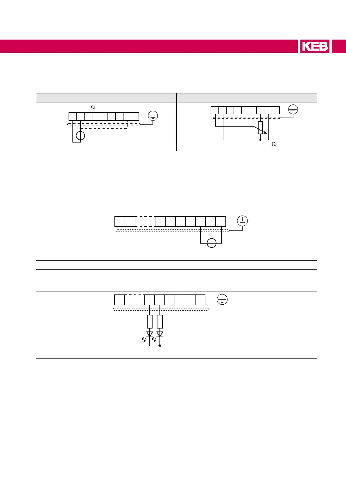
Wiring examples for digital inputs using internal or external voltage.

Connection of the Control: Analog and Power Inputs

Analog inputs configuration

Wiring examples for analog inputs using external or internal setpoints.

External power supply input

Procedure for connecting an external voltage supply to the control board.

Connection of the Control: Output Connections

Digital outputs configuration

Wiring diagram for digital outputs.

Relay outputs configuration

Wiring and protection for relay outputs.

Analog outputs configuration

Wiring diagram for analog outputs.

Voltage output configuration

Wiring for voltage output used for control elements.

Operation of the Control: Basic Operation Modes

Operation without operator

Using a special cable for remote operation via PC.

Operation with digital operator

Description of the optional digital operator for local control.

Operation of the Control: Keyboard and Password Operations

Keyboard operation details

Navigating menus, changing parameters, and resetting errors.

Password input and modes

Understanding the password protection levels and access modes.

Operation of the Control: Interface Operator

Interface operator overview

Features of the interface operator including serial and diagnostic ports.

HSP5 diagnostic and parameter interface

Description of the X6B interface for PC communication.

Operation of the Control: Communication Interfaces

RS232/485 interface description

Pinout and signal meaning for the X6C interface.

RS232 and RS485 connection

Instructions for connecting PCs to RS232 and RS485 interfaces.

Operation of the Control: Communication Configurations

RS485 wiring configurations

Diagrams for full duplex and half duplex RS485 wiring.

Remote control options

Information on operators for remote control applications.

Dimensioning: General Instructions

Dimensioning instructions

Guidelines for sizing the COMBIVERT F5 AIC based on input current.

Dimensioning: Drive Converter Technical Data

Technical data for COMBIVERT drive converters

Table of technical specifications for sizing drive converters.

Dimensioning: AIC Device Technical Data

Technical data for COMBIVERT F5 AIC devices

Specific data for AIC devices, including charging currents.

Cooling System: Liquid-Cooled Device Installation

Installation of liquid-cooled devices

Procedures for installing liquid-cooled drive converters.

Heat sink and operating pressure

Specifications for heat sinks and maximum operating pressure.

Cooling System: Coolant Properties

Materials in the cooling circuit

Compatibility of materials with coolants to prevent corrosion.

Requirements on the coolant

Coolant quality standards, pH, and additive recommendations.

Cooling System: Temperature and Condensation Management

Coolant temperature management

Guidelines for maintaining optimal coolant temperatures.

Moisture condensation prevention

Warnings and precautions against moisture condensation.

Cooling System: Connection and Flow Rate

Connection to the cooling system

Recommendations for connecting to closed or open cooling circuits.

Pressure drop of heat sink vs. flow rate

Graph showing pressure drop based on coolant flow rate.

Cooling System: Circuit Connection Schemes

Series connection scheme for cooling circuits

Diagrams for master/slave and master/slave/slave cooling circuit connections.

Volume flow vs. heat dissipation/temperature difference

Graph illustrating flow rate requirements based on heat load.

Parallel connection scheme for cooling circuits

Diagrams for parallel cooling circuit connections.

Cooling System: Decommissioning

Decommissioning of cooling circuit

Procedures for emptying and preparing the cooling circuit for storage.

Revision History

Revision history table

List of document versions, dates, and changes.

Related product manuals