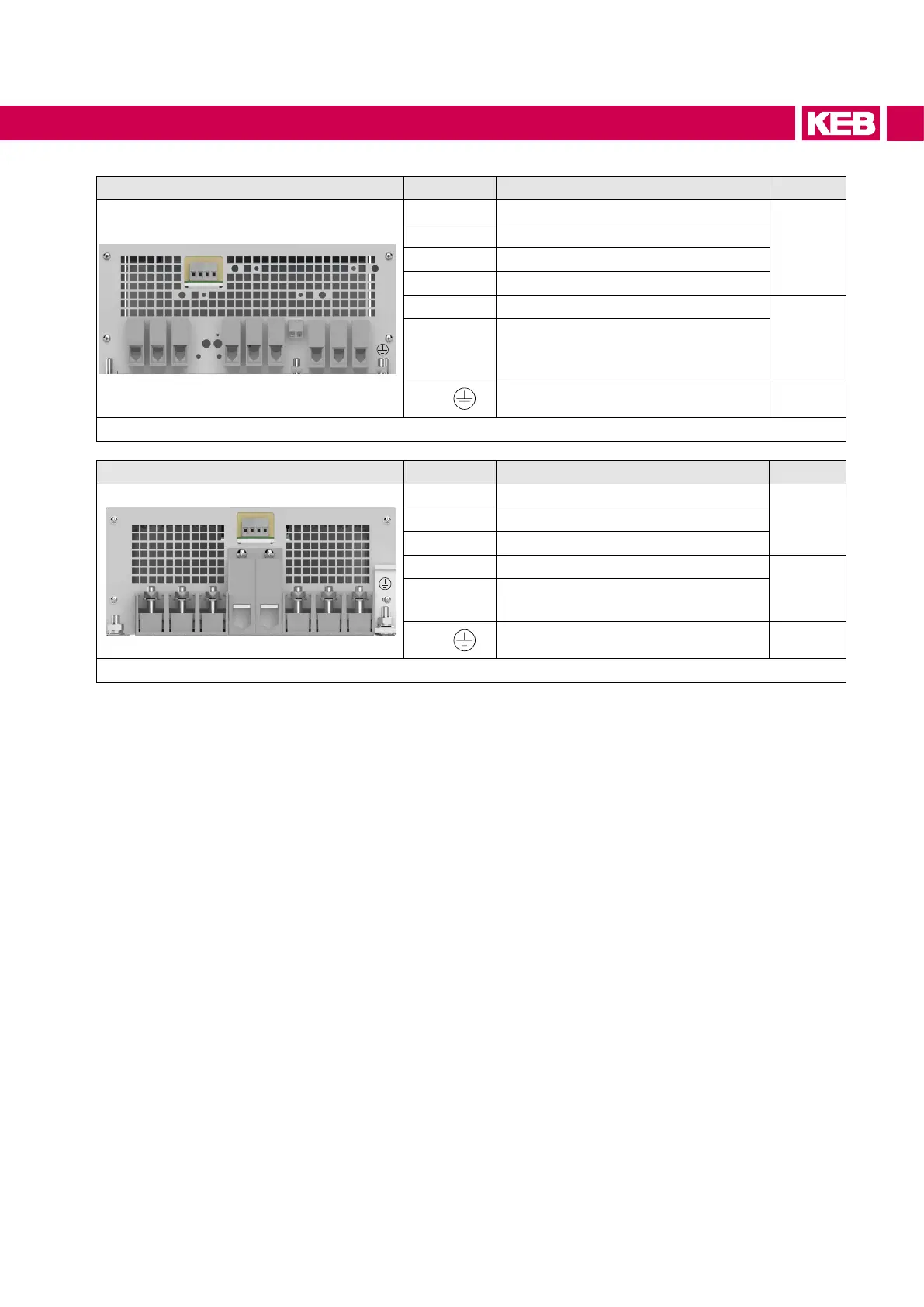
Housing R Name Function Terminal
L1 L2 L3 U V W
+PA
-
K1K2 T1 T2
PB
L1, L2, L3 3-phase mains connection
7 / 8
U, V, W AIC mains connection
+PA, PB Connection for braking resistor
+PA, – Connection for DC-bus connection
T1, T2 Connection for temperature sensor
9
K1, K2
Monitoring of the braking transistor
(GTR7) in connection with terminals
T1, T2 (only at water-cooling systems)
PE,
Connection for protective earth 10
Figure 5: Terminal blocks housing R
Housing U Name Function Terminal
L1 L2 L3 U V W
+
-
K1K2 T1T2
L1, L2, L3 3-phase mains connection
12U, V, W AIC mains connection
+, – Connection for DC-bus connection
T1, T2 Connection for temperature sensor
9
K1, K2
Monitoring of the braking transistor
(GTR7)
PE,
Connection for protective earth 10
Figure 6: Terminal blocks housing U
37
CONNECTION OF THE COMBIVERT F5-AIC
 Loading...
