5 Installation
5.1 EMC-compatible control cabinet installation
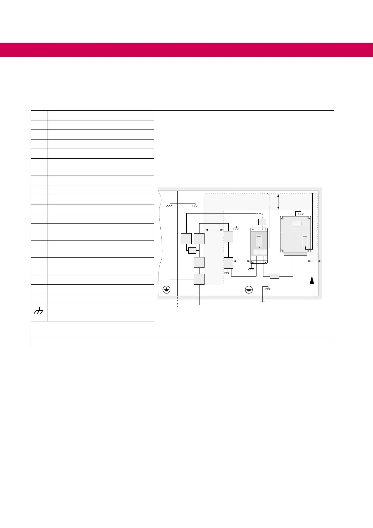
1a Mains fuse
150 mm
30 mm
150 mm
1a
5a
2a
2b
6
7
9b
8
9c
9a
10
10a
11
5
3
4
1b
150 mm
1b Pre-charging fuse
2a Pre-charging contactor
2b Maincontactor(beforeLCLlter)
3 EMClter
4 AIC/LCLlter(ifnecessaryintegrat-
ed in 4)
5 COMBIVERT F5-AIC
5a If necessary external load-shunt
6 External DC fuses
7 Drive converter
8 Motor cable
9a Power unit equipotential bonding
with the housing earth
9b Protective Earth (PE) on the mount-
ing plate power circuit
9c Protective Earth (PE) on the mount-
ing plate control circuit
10 Mains connection power circuit
10a
Mains connection control circuit
11 Control lines
Large area contact at the mounting
plate
Control circuit Power circuit Direction of the
coolingns
Table 14: EMC-compatible control cabinet installation
5.2 Installation instructions
• Stationarily install and earth COMBIVERT.
• Allowforsucientheatdissipationifinstalledinadust-proofhousing.
• Install the COMBIVERT in an appropriate housing in accordance with the local reg-
ulations when operating it in explosion-endangered spaces.
• Protect COMBIVERT against conductive and aggressive gases and liquids.
• TheAIC/LCLltermustbeplacedintheimmediatevicinityoftheAIC.
• The drive converters must be placed in the immediate vicinity of the AIC.
• The DC connection lines must be kept as short as possible.
• The use of ferrites on the DC line is not permitted.
34
INSTALLATION
 Loading...
