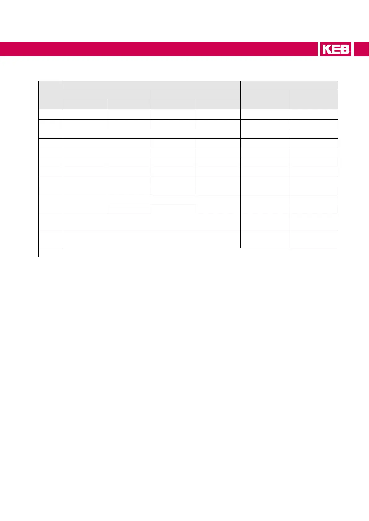
6.2.1 Cross-sections and tightening torques of the terminals
No.
Permissible cross-section exible with wire-end ferrule Tightening torques
mm² AWG
Nm lb inch
min max min max
1 0.25 4 24 10 0.6 5
2 0.25 1.5 26 14 0.6 5
3 Screw M4 for ring crimp connector 1.3 11
4 6 16 22 8 1.2 11
5 2.5 35 12 2 4.5 40
6 0.5 2.5 21 12 0.6 6
7
1)
16 50 6 AWG 1/0 MCM 6…8 75
8
2)
35 90 4 AWG 2/0 MCM 15...20 180
9 0.2 4 24 AWG 10 AWG 0.6 5.3
10 10 mm stay bolt for ring crimp connector 25 220
11 50 150 1/0 AWG 300 MCM 25…30 270
12
10 mm stud for ring crimp connector and for DC connection
50...150 qmm
25 220
13
12 mm stud for ring crimp connector
max. 2 ring crimp connectors with 240 mm² for each
35 310
Table 16: Cross-sections and tightening torques of the terminals
1)
Line applies to F5 housing R device size 20.
2)
Line applies to F5 housing R device size 22.
39
CONNECTION OF THE COMBIVERT F5-AIC
 Loading...
