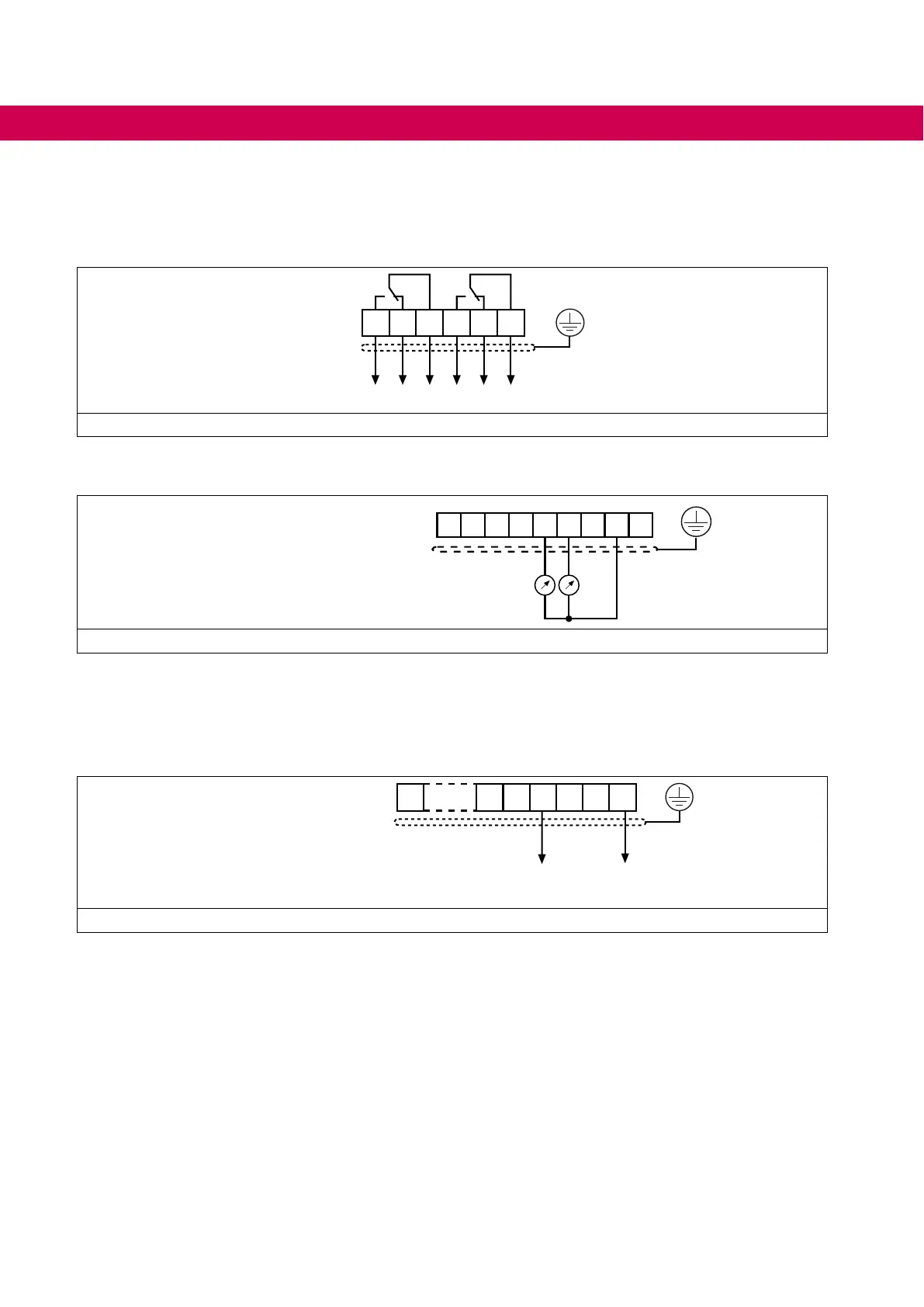
EasyManuals Logo
Home>KEB>Inverter>COMBIVERT 19F5 Series

KEB COMBIVERT 19F5 Series User Manual

KEB COMBIVERT 19F5 Series
72 pages
To Next Page IconTo Next Page
To Previous Page IconTo Previous Page
Page #52 background imageLoading...
Page #52 background image
7.1.7 Relay outputs
In case of inductive load on the relay outputs a protective circuit must be provided (e.g.
free-wheeling diode)!
24 25 26
X2A
27 28 29
max. 30 V DC / 1 A
Figure 19: Relay outputs
7.1.8 Analog outputs
Uout: 0...±10 V DC
I
max: 10 mA
X2A 1 2 3 4 5 6 7 8 9
Figure 20: Analog outputs
7.1.9 Voltage output
The voltage output is used to control the digital inputs and for the supply of external
control elements. The maximum output current of 100 mA mA may not be exceeded.
10 18 19 20
X2A
21 22 23
+-
ca. 24V DC / max. 100 mA
Figure 21: Voltage output
52
CONNECTION OF THE CONTROL

Table of Contents

Questions and Answers:

Question and Answer IconNeed help?

Do you have a question about the KEB COMBIVERT 19F5 Series and is the answer not in the manual?

KEB COMBIVERT 19F5 Series Specifications

General IconGeneral
BrandKEB
ModelCOMBIVERT 19F5 Series
CategoryInverter
LanguageEnglish

Related product manuals