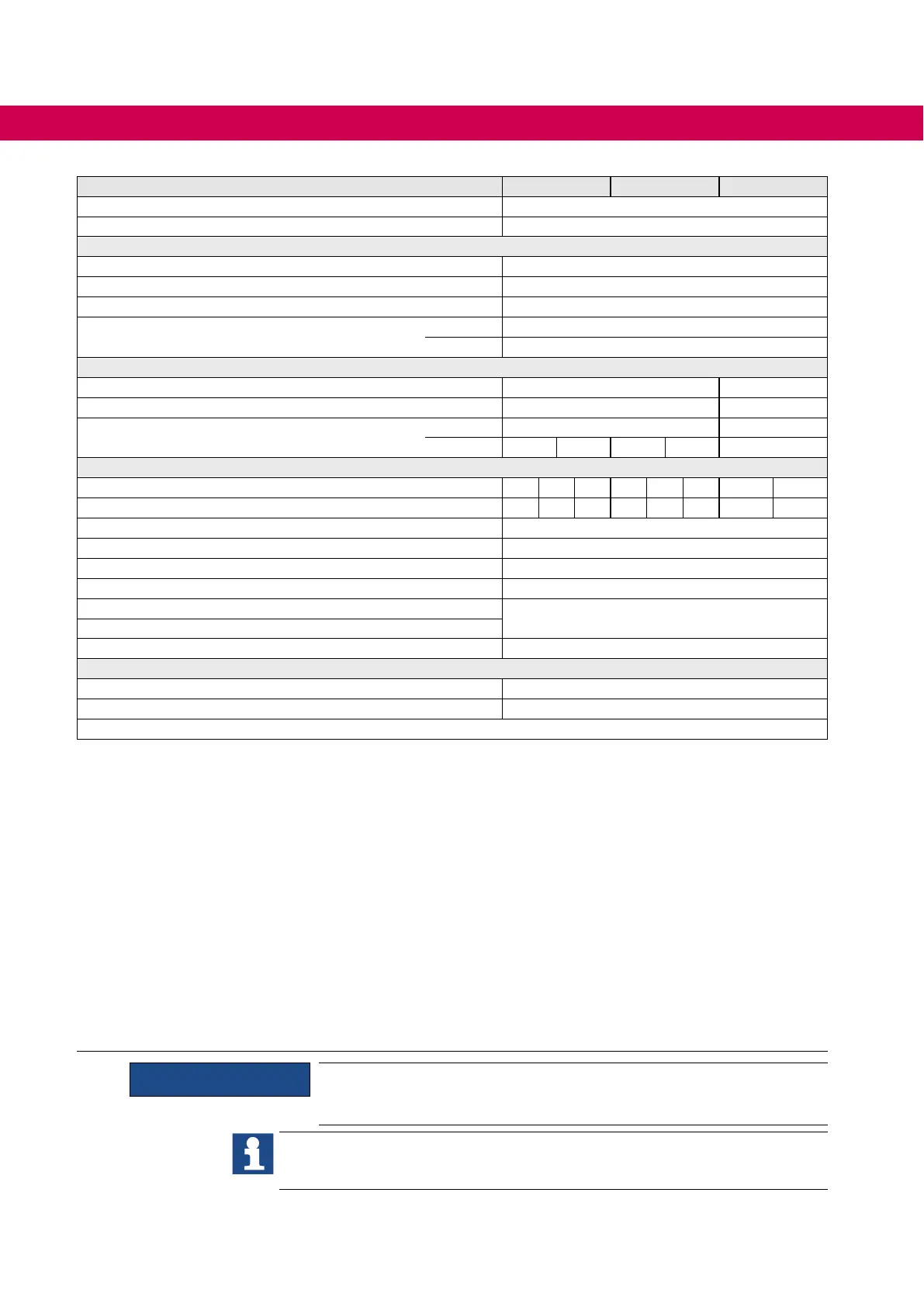
Inverter size 28 29 30
Housing P
Module number 1
Braking option
Min. braking resistor
10)
R_min / Ω 2.1
Max. braking current
10)
IB_max / A 380
Switching level braking transistor U
B_dc / V 780
Monitoring braking transistor (K1 / K2)
11)
Umon_dc / V 24
I
mon_dc / A 2
Operating conditions air cooler
Switching frequency f
S / kHz 2 –
Max. heat sink temperature (OH)
16)
t_max / °C 90 –
External fan power supply
U
ext_dc / V
24
–
I
ext_dc / A
2.5 4
15)
2.5 4
15)
–
Operating conditions liquid cooler
Switching frequency f
S / kHz 2 4 8 2 4 8 2 4
Max. heat sink temperature (OH)
16)
t_max / °C 90 73 60 90 73 60 90 73
∆Tow/returnow
ΔT / K 3...6
Flow temperature typical t
in_typ / °C 25
Flow temperature maximum t
in_max / °C 40
Liquid cooler content V
/ l 0.8
Volumeow Q
/ l/min
=> Diagrams of the cooling design
Pressure drop Δ
pv / bar
Max. permissible operating pressure p
_max / bar 10
Other data
Max. weight air cooler m
_max / kg 97.5
Max. weight liquid cooler m
_max / kg 96
Table 7: Technical data of the 400V class - Single Drive
1) Restrictions when using HF lters.
2) Phase conductor grounded mains are only permissible without HF lters.
3) Protection in accordance with UL => Protection of drive converters.
4) The voltage at the motor is dependent on the series-connected units and on the control method.
5) The output frequency is to be limited in such way that 1/10 of the switching frequency is not exceeded.Devices with higher maxi-
mum output frequency are subject to export restrictions and are only available upon request.
6) Max. current before the OL2 function triggers.
7) With the regulated operating modes 5 % are to be subtracted as control reserve.
8) Applies to rated input voltage 400 V, 25 °C ambient temperature.
9) Maximum additional chargeable capacity per module.
10) Data apply to a switching level for the braking transistor of 780 V DC.
11)
=> Wiring Diagrams.
UL, C-UL E120782 UL508, CSA C22.2 No.14; UL1604 (class I, Division 2, Group A, B, C, D); 277V AC 8 A,
General use, 24 V DC 6 A, General use, B300, R300 250 V AC / max. 2 A, 24 V DC / max. 2 A (Pilot Duty).
12) 180 % only at rated switching frequency.
13) The internal fans are switched off below the operating voltage range.
14) Only possible as DC version without precharging.
15)
The use of stronger heat sink fans for adaption to the ambient conditions or at higher overload (180 %) is possible after consultation
with KEB.
16) The specications apply to devices without derating of the switching frequency.
17) The specications only apply if there is parallely no power output via the motor connection terminals U / V / W.
ATTENTION
An input choke is absolutely necessary.
The technical data are for 2/4-pole standard motors. With other pole numbers
the drive converter must be dimensioned onto the rated motor current. Contact
KEB for special or medium frequency motors.
30
TECHNICAL DATA 400V CLASS
 Loading...


