EasyManuals Logo
Home>KEB>DC Drives>COMBIVERT F5

KEB COMBIVERT F5 Instructions For Use

KEB COMBIVERT F5
104 pages
To Next Page IconTo Next Page
To Previous Page IconTo Previous Page
Page #82 background imageLoading...
Page #82 background image
7 Wiring Diagrams
7.1 Unit size 28...30
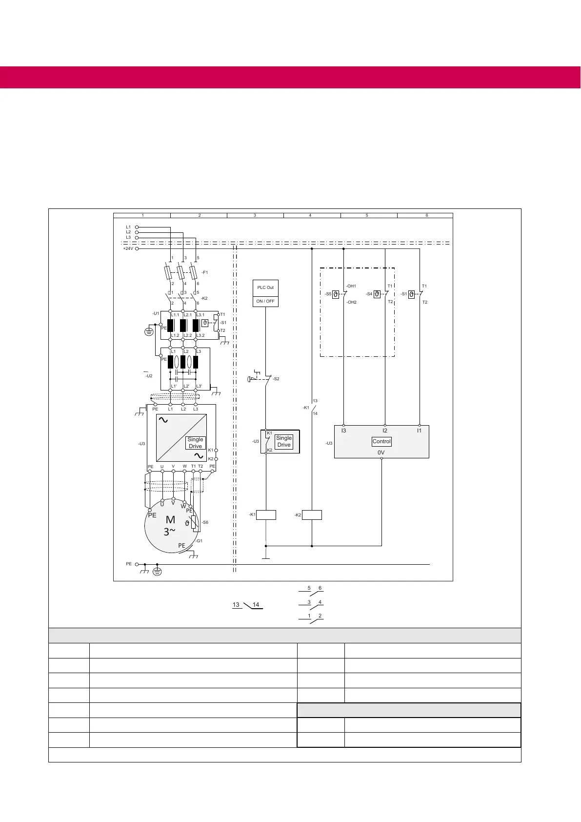
7.1.1 Mains and control connection
-F1
-K2
-U1
-U2
-U3
-S1
-S6
-G1
-K1
-U3
-K2
-K1
13
14
1
2
3
4
5
6
L1
L2
L3
+24V
ϑ
-OH1
-OH2
ϑ
T1
T2
-S5
-S1
PE
ϑ
T1
T2
-S4
PE
L1
L2
L3
L1'
L2'
L3'
L1
L2
L3
U
V
W
PE
T1
T2
PE
Single
Drive
K1
K2
Single
Drive
K2
K1
M
3~
U
V
W
PE
ϑ
PE
1
3
5
2
4
6
1
3
5
2
4
6
L1.1
L2.1
L3.1
L1.2
L2.2
L3.2
PE
ϑ
T1
T2
PE
PE
-S2
-U3
ON / OFF
PLC Out
I1
I2
I3
0V
Control
14
13
82.4
1
3
5
2
4
6
82.2
Legend
F1 Mains fuse S1 Temperature switch mains choke
K1 Coupling relay S2 Emergency stop button / switch
K2 Main contactor S6 Temperature switch motor
U1 Mains choke G1 Motor
U2 HFlter Optional
U3 COMBIVERT single drive S4 Temperature switch motor choke
DO1 PLC digital output S5 Temperature switch braking resistor
Figure 30: Mains and control connection
82
WIRING DIAGRAMS

Table of Contents

Other manuals for KEB COMBIVERT F5

Questions and Answers:

Question and Answer IconNeed help?

Do you have a question about the KEB COMBIVERT F5 and is the answer not in the manual?

KEB COMBIVERT F5 Specifications

General IconGeneral
BrandKEB
ModelCOMBIVERT F5
CategoryDC Drives
LanguageEnglish

Related product manuals