5.2.4 Parallel connection of liquid coolers
• Volumeowasafunctionoftotalpowerdissipationandtemperaturedifference.
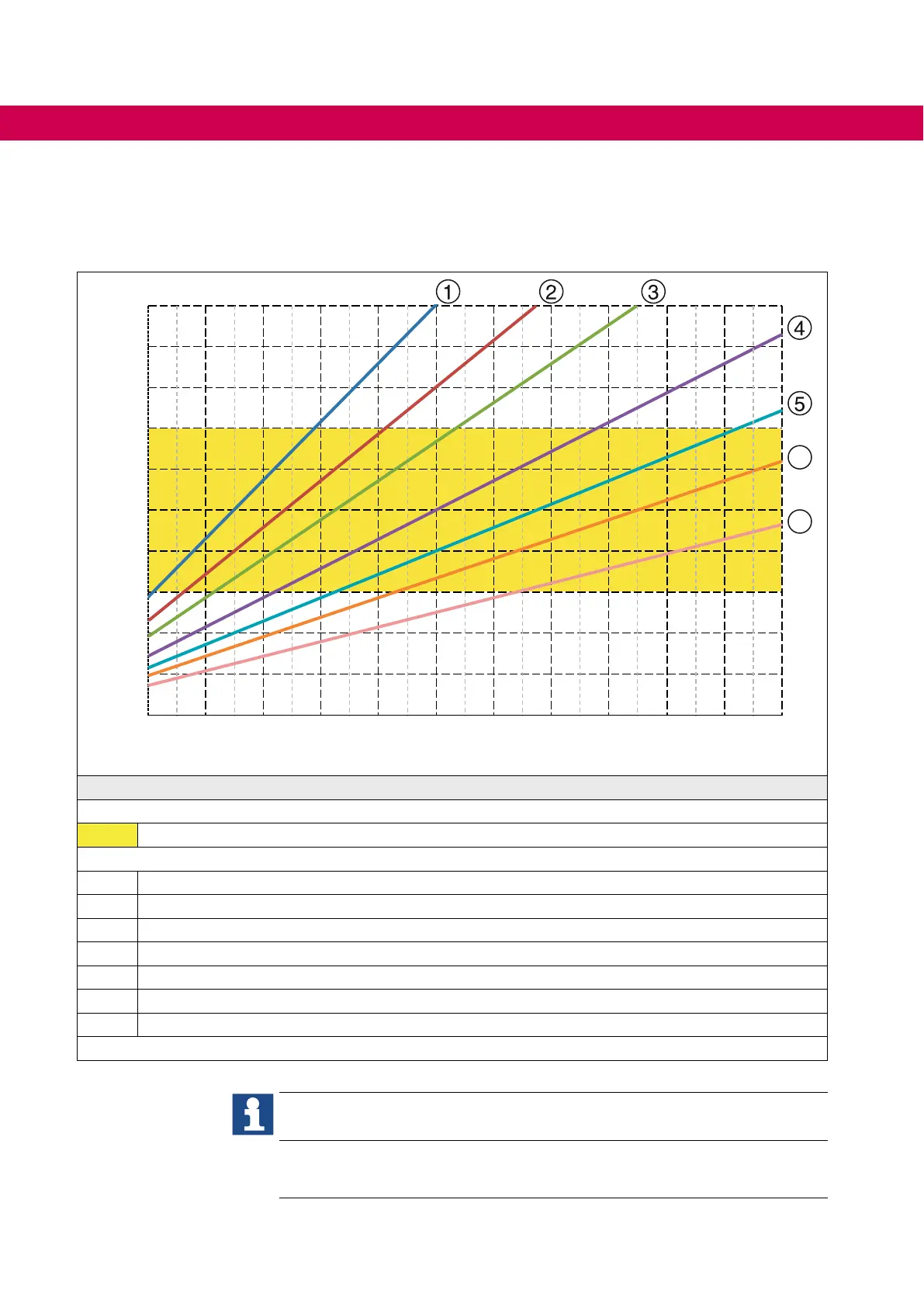
• The diagram below applies to the parallel connection of liquid coolers.
Temperature dierence ∆T in K
0
1
2
3
4
5
6
7
8
9
10
4 6 8 10 12 14 16 18 20 22 24 26
6
7
Total power dissipation Pv in kW
Legend
Recommended working range
∆T = 3...7 K
Volume ow
1 20 l/min
2 25 l/min
3 30 l/min
4 40 l/min
5 50 l/min
6 60 l/min
7 80 l/min
Figure 15: Volume ow and temperature difference for parallel connection
Thepoints1...7areeachbasedonthetotalvolumeowofthedriveconverter
system.
Thetotalvolumeowshouldbedividedbythenumberofmodules.Thede-
terminedvalueforthevolumeowissetforeachmodulebymeansofthrottle
valves.
62
OPERATION OF LIQUID-COOLED DEVICES
 Loading...


