Front Panel Operation
2-31
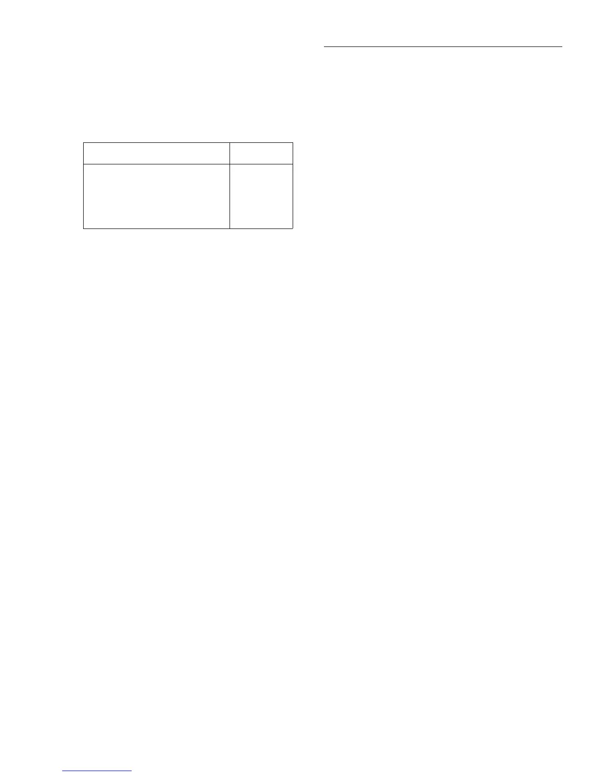
AUTO: Refer to Table 2-20 for the resolution associated
with the integration time.
OFFSETCOMP
Offset compensation is used to compensate for voltage
potentials, such as thermal offsets, across the device under
test. This feature eliminates errors due to a low level external
voltage source configured in series with the unknown resis-
tor. Offsets up to ±0.2V on the 20Ω and 200Ω ranges, and
from -0.2V to +2V on the 2kΩ and 20kΩ ranges can be cor-
rected with offset compensation. Offset compensation is
available for 2- and 4-wire resistance measurements.
During offset compensated resistance measurements, the
Model 2002 performs the following steps for each A/D con-
version:
1. Makes a normal resistance measurement of the device.
In general, this consists of sourcing a current through
the device, and measuring the voltage drop across the
device.
2. Turns off the internal current source and again measures
the voltage drop across the device. This is the voltage
caused by an external device.
3. Calculates and displays the corrected resistance value.
Offset compensation not only corrects for small error
voltages in the measurement circuit, but it also compensates
for thermal voltages generated within the Model 2002.
Consequently, the use of offset compensation yields greater
accuracy.
The OFFSETCOMP selections are explained as follows:
ON: Enables offset compensation
OFF: Disables offset compensation
Offset compensated readings are indicated by “OCmp” to
the right of the reading.
Table 2-20
Ω
2 and
Ω
4 auto resolution
Integration time Resolution
0.01 to <0.02 PLC
0.02 to <0.10 PLC
0.10 to <1.00 PLC
1.00 to <10.00 PLC
10.00 to 50 PLC
4.5d
5.5d
6.5d
7.5d
8.5d
Note: If the resolution is AUTO and the integration time SET-
BY-RSLN, the resolution will be 7.5 digits and the integration
time 1.0 PLC.
Note that the offset compensation settings of the ohms func-
tions are discrete. Thus, enabling offset compensation in 2-
wire ohms has no effect on 4-wire ohms.
MAXAUTORANGE
By setting an upper limit on autoranging, you can prevent
changes to ranges that you do not want to use. This speeds up
the reading rate while still using auto-ranging.
MAXAUTORANGE selections for Ω2 and Ω4:
1GΩ, 200MΩ, 20MΩ, 2MΩ, 200kΩ or 20kΩ: Sets maxi-
mum autorange limit for Ω2.
2MΩ, 200kΩ, 20kΩ, 2kΩ, 200Ω or 20Ω: Sets maximum
autorange limit for Ω4.
Multiple displays
There are three multiple displays available just for the resis-
tance functions:
• Source current
• Voltage drop
• Lead resistance (Ω4 only)
Source current: This is the value of the current being
sourced for the present resistance range. It is based on the
calibration constants and is shown as follows:
Source Current = 0.0000 mA
Voltage drop: This display shows the voltage drop across the
resistance under test. It is shown as follows:
Voltage Drop = 0.0000 mV
This voltage drop is determined by multiplying the source
current by the resistance and does not include voltage contri-
butions from other current that may be flowing through the
resistance.
Lead Resistance: This display, available only for 4-wire
ohms, shows the value of the lead resistance that is being
nulled by using the Ω4 function. You can use the information
to decide if a 4-wire measurement is necessary. The display
is as follows:
Lead Resistance = 0.0000 Ω
If the lead resistance exceeds 1kΩ, the display is:
2-WIRE OHMS measurement overflow

 Loading...


