Front Panel Operation
2-51
Meter complete
The METER COMPLETE OUTPUT jack provides a TTL-
compatible output pulse that can be used to trigger other
instruments. The specifications for this trigger pulse are
shown in Figure 2-15.
Typically, you would want the Model 2002 to output a trig-
ger after the settling time of each measurement. (Settling
time includes the internally set measurement settling time
and the user programmed DELAY period.) An output com-
pletion pulse occurs after each measurement as long as the
measure source is set to external, timer, manual, or immedi-
Figure 2-15
Meter complete and asynchronous trigger link output pulse
specifications
Meter
Complete
TTL High
(3.4V Typical)
TTL Low
(0.25V Typical)
10µs
Minimum
ate. See paragraph 2.7.2 for details on programming the mea-
sure layer.
The Model 2002 can also output a completion pulse while in
the scan and/or arm layers of operation. Figure 2-12 shows
where these triggers occur in the trigger model. If the scan
layer Source Bypass is enabled (Control = Source) and the
Scan Source is programmed for External, an output trigger
occurs on each return path through the scan layer. If the arm
layer Source Bypass is enabled (Control = Source) and the
Arm Source is programmed for External, an output trigger
occurs on each return path through the arm layer. See para-
graphs 2.7.3 and 2.7.4 for programming the Scan and arm
layers.
External triggering example #1
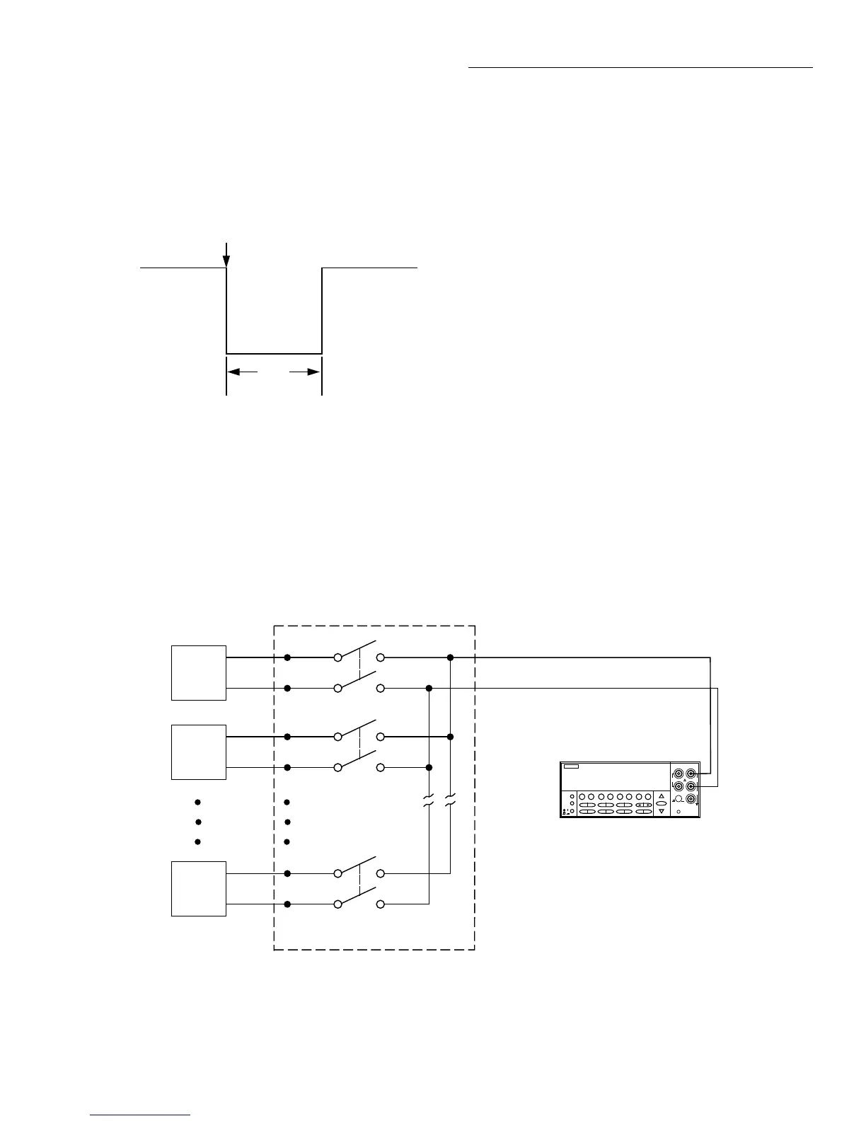
In a typical test system, you may want to close a channel and
then measure the DUT connected to that channel with a mul-
timeter. Such a test system is shown in Figure 2-16, which
uses a Model 2002 Multimeter to measure ten DUTs
switched by a Model 7011 multiplexer card in a Model 7001
or 7002 Switch System.
The external trigger connections for this test are shown in
Figure 2-17. Channel Ready (output) of the Model 7001 or
7002 is connected to External Trigger Input of the Model
2002. Meter Complete Output of the Model 2002 is con-
nected to External Trigger (input) of the Model 7001 or
7002.
Figure 2-16
DUT test system
NEXT
DISPLAY
PREV
POWER
2002 MULTIMETER
SENSE
Ω 4 WIRE
HI
INPUT
LO
INPUTS
CAL
500V
PEAK
F
R
FRONT/REAR
2A 250V
AMPS
350V
PEAK
1100V
PEAK
2002 Multimeter
1
DUT
#1
2
DUT
#2
10
DUT
#10
OUTPUT
Card 1
7011 MUX Card
Input HI
Input LO

 Loading...


