External Triggering (Model 2306-VS Only) 6-3
Figure 6-1
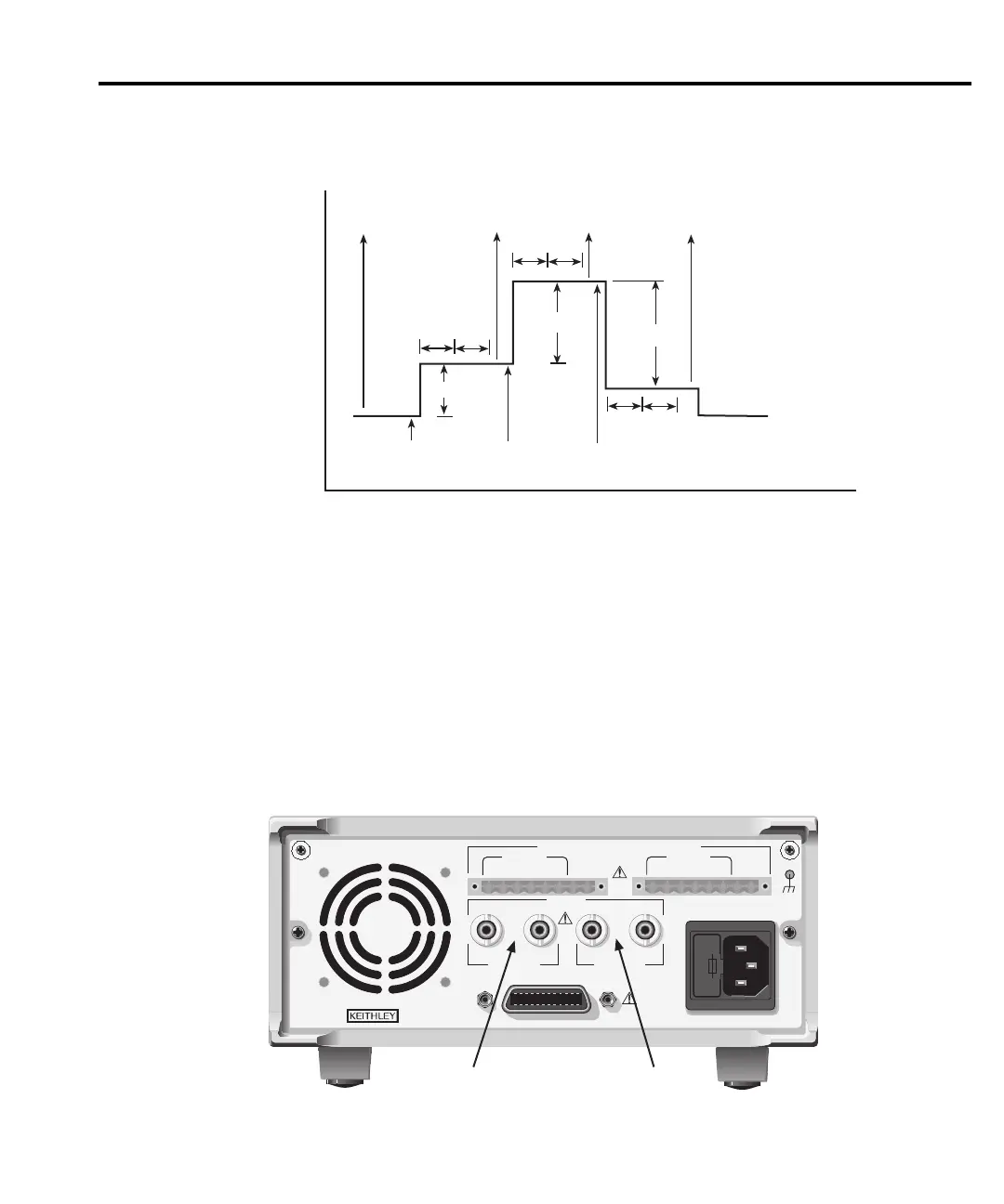
Typical trigger sequence
Step
Step
Trigger
In (2)
Trigger
Out (6)
Trigger
In (7)
Trigger
In
Trigger
Out
Trigger
Out
Output
Voltage
Delay
Meas.
Delay
Meas.
Delay = Programmed Delay
Meas. = Measurement Period
Time
Trigger
Out (1)
Step (3)
Delay
(4)
Meas.
(5)
Numbered sequence shown
on first step correspond to
steps in “Typical trigger
sequence” (see text).
Trigger connections
Trigger connectors
The rear panel of the Model 2306-VS shows the trigger connectors (Figure 6-2). Note that
each channel includes a TRIGGER IN and TRIGGER OUT BNC connector. Use only quality
50Ω
coaxial cable for all trigger connections to ensure proper operation.
Figure 6-2
Model 2306-VS rear panel trigger connectors
WARNING:NO INTERNAL OPERATOR SERVICABLE PARTS,SERVICE BY QUALIFIED PERSONNEL ONLY.
CAUTION:FOR CONTINUED PROTECTION AGAINST FIRE HAZARD,REPLACE FUSE WITH SAME TYPE AND RATING.
MADE IN
U.S.A.
LINE RATING
100-120VAC,
200-240VAC
50, 60 HZ
165VA MAX.
LINE FUSE
SLOWBLOW
2.0A, 250V
IEEE-488
+++
____
+
DVM IN
OUTPUT #2
SOURCE SENSE SOURCE
+++
____
+
DVM IN
OUTPUT #1
SOURCE SENSE SOURCE
ISOLATION FROM EARTH: 22 VOLTS MAX.
DVM IN
+30 VDC MAX.
TRIGGER
CAT I
IN OUT IN OUT
CHANNEL 1 CHANNEL 2
Channel 1
Trigger Connectors
Channel 2
Trigger Connectors
Test Equipment Depot - 800.517.8431 - 99 Washington Street Melrose, MA 02176
TestEquipmentDepot.com
 Loading...


