2-20 Basic Power Supply Operation
Figure 2-3
+ sense
- sense
+ output
- output
Model 2306
Charger Circuit
R
S
V
S
V
Charger
R
Cable
R
Cable
V
C
R
C
V
Supply
I
Sink
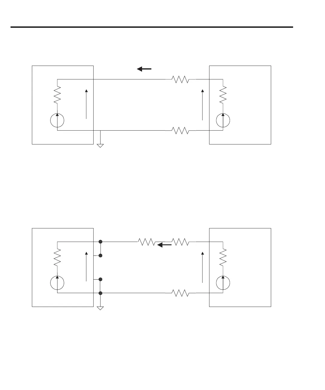
Sink operation
However, in this configuration current compliance may not be reached and current measure-
ments may be unstable if I
sink
R
cable
is large. Figure 2-4 shows a preferred method for measuring
the current output of the charger circuit at a rated output voltage with the power supply operating
in loc
al sense mode. Set the supply output voltage to 0.00V and the enter the desired test (com-
pliance) current, I
test
. Select R
test
so that V
charger
, the desired test voltage, is the product of I
test
and R
test
.
Figure 2-4
+ sense
- sense
+ output
- output
Model 2306
Charger Circuit
R
S
V
S
V
Charger
R
Cable
R
Cable
V
Supply
= 0
R
Test
V
C
R
C
I
Sink
Preferred method
NOTE Figure 2-4 shows the preferred method for measuring current output of the charger
circuit at a rated output voltage with the power supply operating in local sense mode.
Unless high speed transient performance is absolutely required when operating as a sink, the
LO
W bandwidth output mode provides superior results with a constant current or voltage load
such as a battery charger.
Test Equipment Depot - 800.517.8431 - 99 Washington Street Melrose, MA 02176
TestEquipmentDepot.com
 Loading...


