SECTION 2
Getting Started
Binding Post
Interlock
IEEE-488 Connector
Note : Use shielded IEEE-488 cable
Line Power Input
WARNING : Connect to
grounded outlet using
%wirs power cord
- Line Voltage Switch
105v-125v
210-250”
,n^+;..“..l ‘-41rmer
~~l-.~--.-. -_ .lOV,
1 SO-22OV operation)
CAUTION : Ooeration
Cur& input r0s’s
1 Out = Calibration disabled 1
on Improper I&
Voltage may damage
““II
Line Fuse
CAUTION : Replace fuse
with one of 8ame type and
rating : f/z?A. go-12Sv
l/4 A, 180-250v
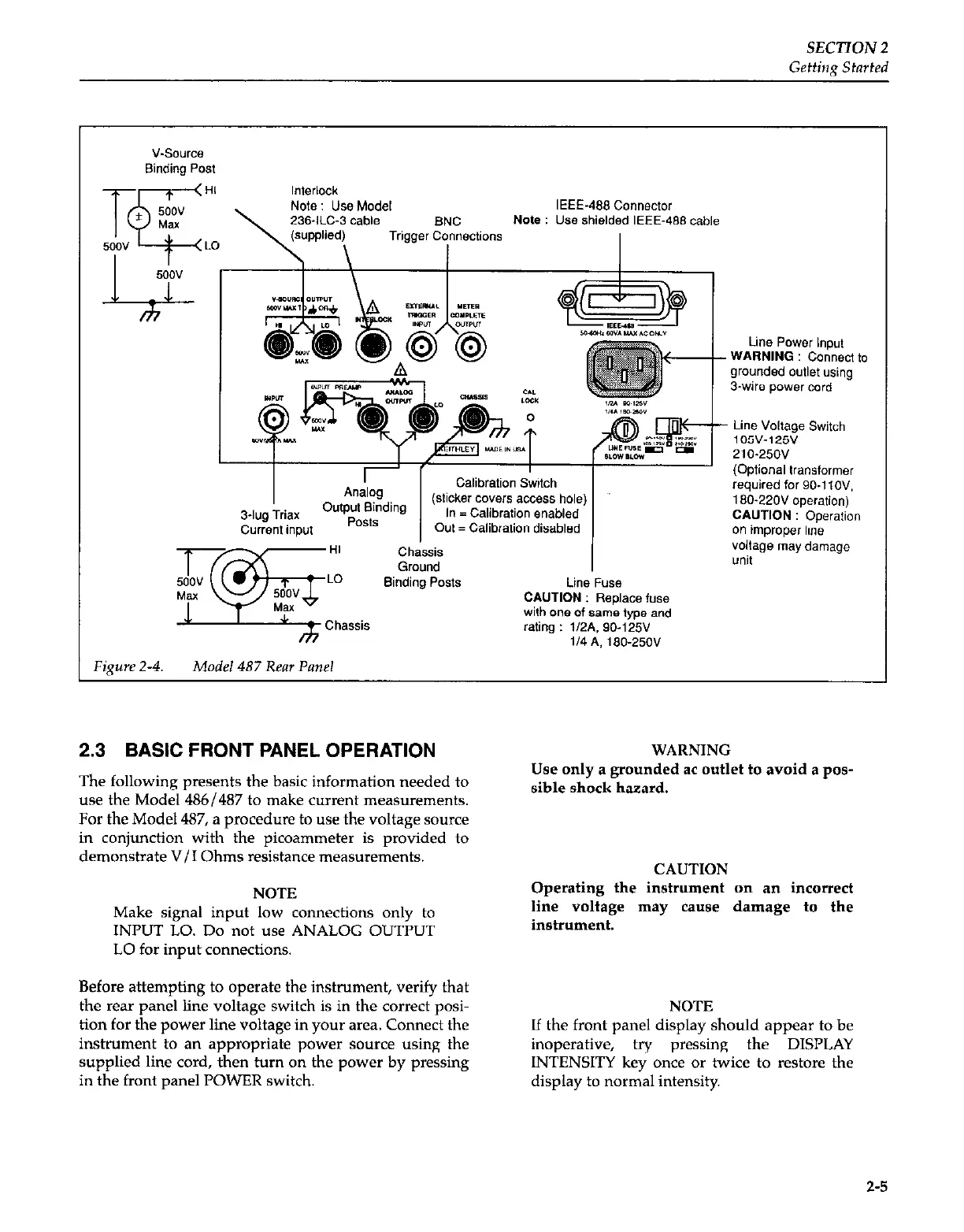
Fipre 2-4.
Model 487 Rear Panel
2.3 BASIC FRONT PANEL OPERATION
The following presents the basic information needed to
use the Model 486/487 to make current measurements.
For the Model 487, a procedure to use the voltage source
in conjunction with the picoammeter is provided to
demonstrate V/I Ohms resistance measurements.
NOTE
Make signal input low connections only to
II’UT LO. Do not use ANALOG OUTPUT
LO for input connections.
Before attempting to operate the instrument, verify that
the rear panel line voltage switch is in the correct posi-
tion for the power line voltage in your area. Connect the
instrument to an appropriate power source using the
supplied line cord, then turn on the power by pressing
in the front panel POWER switch.
WARNING
Use only a grounded ac outlet to avoid a pos-
sible shock hazard.
CAUTION
Operating the instrument an an incorrect
line voltage may cause damage to the
instrument.
NOTE
If the front panel display should appear to be
inoperative,
try pressing the DISPLAY
INTENSITY key once or twice to restore the
display to normal intensity.
2-5
 Loading...


