SECTION 3
Front Panel Operation
3.16 MEASUREMENT CONSIDERATIONS
The Model 4861487 is a highly sensitive instrument that
can measure very low current levels. At these low signal
levels, a number of factors can affect a measurement.
Some considerations when making measurements with
the Model 486/487 are discussed in the following
paragraphs.
3.16.1 Source Resistance
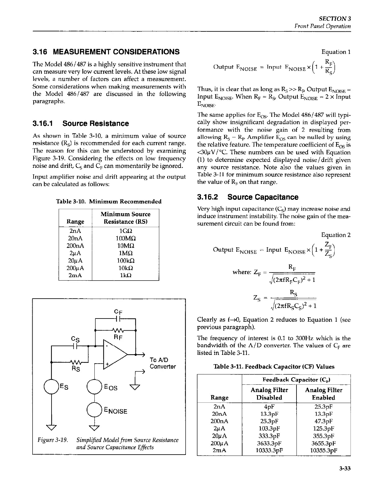
As shown in Table 3-10, a minimum value of source
resistance (R,) is recommended for each current range.
The reason for this can be understood by examining
Figure 3-19. Considering the effects on low frequency
noise and drift, C, and C, can momentarily be ignored.
Input amplifier noise and drift appearing at the output
can be calculated as follows:
Table 3-10. Minimum Recommended
Resistance (RS)
EOS
ENolsE
Figure 3-19.
Simplified Modelfrom Source Resistance
and Source Capacitance Effects
Equation 1
Output E,,,,, = Input ENOISE x 1 + -
( 3
Thus, it is clear that as long as R, >> R, Output ENolsE =
Input E,,,,,. When R, = R, Output ENOISt = 2 x Input
hXX.
The same applies for E,,. The Model 486/487 will typi-
cally show insignificant degradation in displayed per-
formance with the noise gain of 2 resulting from
allowing R, = R, Amplifier E,, can be nulled by using
the relative feature. The temperature coefficient of E, is
<3O~V/“C. These numbers can be used with Equation
(1) to determine expected displayed noise/drift given
any source resistance. Note also the values given in
Table 3-11 for minimum source resistance also represent
the value of R, on that range.
3.16.2 Source Capacitance
Very high input capacitance (CJ may increase noise and
induce instrument instability. The noise gain of the mea-
surement circuit can be found from:
Equation 2
Output ENOISE = Input ENOISE
++z,
where: zF = J&
zs=&i&Y
Clearly as f+O, Equation 2 reduces to Equation 1 (see
previous paragraph).
The frequency of interest is 0.1 to 300Hz which is the
bandwidth of the A/D converter. The values of C, are
listed in Table 3-11
Table 3-11. Feedback Capacitor (CF) Values
Range
2nA
20nA
2oonA
2~4
20~A
ZOOpA
2mA
Feedback C
Analog Filter
Disabled
4pF
13.3pF
25.3pF
103.3pF
333.3pF
3633.3pF
10333.3uF
mcitor CC,)
Analog Filter
Enabled
25.3pF
13.3pF
47.3pF
125.3pF
355.3pF
3655.3pF
10355.3pF
3-33
 Loading...


