SECTION 3
Front Panel Operation
5. Connect the current to be measured to the input of
the Model 486/487 (see Figure 3-4).
6. Disable zero check and read the measured current on
the display of the Model 486/487.
Notes:
1. To prevent the possibility of oscillation, input low
should typically be connected to a common low im-
pedance,suchas chassiioroutputlowifusingthev-
Source of the Model 487. Only use input cables that
are properly shielded and keep
them
as short as pos-
sible.
2. A number of other considerations that could have an
affect on the integrity of current measurements are
discussed in paragraph 3.16.
3.6 USING THE VOLTAGE SOURCE
(Model 487)
The V-Source of the Model 487 can source up to ?z505V at
2.5mA. The available voltage ranges of the V-Source are
summarizedinTable3-7. Thisis afloatingvoltagesource
that is isolated from the chassis and signal common of the
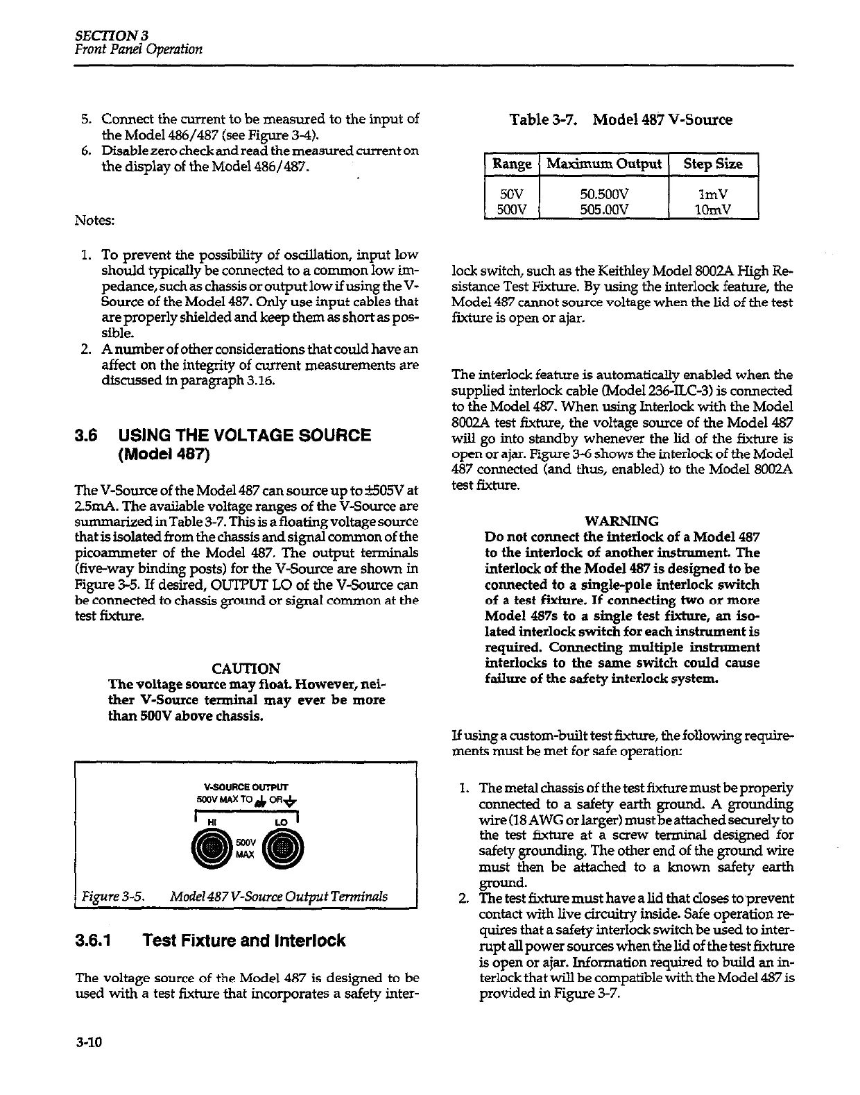
pica-eter of the Model 487. The output terminals
&e-way binding posts) for the V-Source are shown in
Figure 3-5. If desired, OUTPUT LO of the V-Source can
be connected to chassis ground or signal common at the
test fixhlre.
CAUTION
The voltage sauce may fioat. However, nei-
ther V-Source terminal may ever be more
than 5OOV above chassis.
Figure 3-5.
Model 487 V-Source Oufpuf Tennimls
3.6.1 Test Fixture and Interlock
The voltage source of the Model 487 is designed to be
wed with a test fixture that incorporates a safety inter-
Table 3-7. Model 487 V-Source
lock switch, such as the Keithley Model 8002A High Re-
sistance Test Fixture. By using the interlock feature, the
Model 487 cannot source voltage when the lid of the test
fixture is open or ajar.
The interlock feature is automatically enabled when the
supplied interlock cable (Model 236-ILC-3) is connected
to the Model 487. When using Interlock with the Model
8002A test fixture, the voltage source of the Model 487
will go into standby whenever the lid of the fixture is
open or ajar. Figure 3-6 shows the interlock of the Model
487 connected (and thus, enabled) to the Model 8002A
test fixture.
WARNING
Do not connect the interlock of a Model 487
to the interlock of another instrument. The
interlock of the Model 487 is designed to be
connected to a single-pole interlock switch
of a test fixture. If connecting two or more
Model 487s to a single test fixture, an iso-
lated interlock switch for each instrument is
required. Connecting multiple instxumant
interlocks to the same switch could cause
failure of the safety interlock system.
If using a custom-built test fixture, the following require
ments must be met for safe operation:
1. The metal chassis of the test fixture must be properly
co~ected to a safety earth ground. A grounding
wire(l8AWG orlarger)mustbeattachedsecurelyto
the test fixture at a screw terminal designed for
safety grounding. The other end of the grmmd wire
must then be attached to a known safety earth
ground.
2. The test fixture must have a lid that closes toprevent
contact with live circuitry inside. Safe operation re-
quires that a safety interlock switch be used to inter-
rupt alI power sources when the lid of the test fixture
is open or ajar. Information required to build an in-
terlock that will be compatible with the Model 487 is
provided in Figure 3-7.
3-10
 Loading...


