TP-7070 7/18 107Section 5 Accessories
Section 5 Accessories
5.1 Accessories and Connections
Factory-installed accessories are available to help
finalize installation, add convenience to operation and
service, and establish state and local code compliance.
See Figure 5-1 for a list of available kits. Obtain the
most current accessory information from your local
authorized service distributor/dealer.
Kit Description
Analog Input/Output Module
Digital Input/Output Module
Thermocouple Input Module
Remote Serial Annunciator
Figure 5-1 Optional Accessories
This section illustrates several accessories available at
print time of this publication. Accessory kits generally
include installation instructions. See wiring diagrams
manual for electrical connections not shown in this
section. See the installation instructions and drawings
supplied with kit for information on kit mounting location.
The instructions provided with the accessory kit
supersede these instructions where there are
differences. In general, run AC and DC wiring in
separate conduit. Use shielded cable for all analog
inputs. Observe all applicable national, state, and local
electrical codes during accessory installation.
See Section 5.2, Accessory Connections, and the
generator set wiring diagrams for terminal identification.
5.2 Accessory Connections
Connect external optional accessories including
alarms, battery chargers, thermocouples, and remote
switches to the terminal block or modules in the
customer connection box. See Figure 5-2. Do not
attempt to connect directly to the APM802 controller or
base module.
For specific information on accessory connections, refer
to the accessory wiring diagrams in the wiring diagram
manual and the instruction sheet accompanying the kit.
See the generator set wiring diagram for TB10
connections.
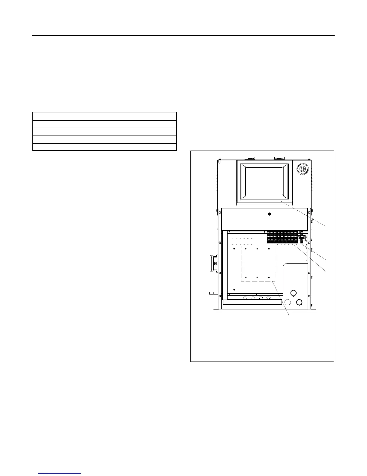
Note: Covers have been removed for illustration.
1. USB port (under hinged panel)
2. 240 VAC / 60 Hz power supply connection
3. Terminal block TB10 for accessory connections
4. Optional module locations
3
2
1
11601000945
4
Figure 5-2 APM802 Controller and Customer
Connection Box
 Loading...

