TP-7070 7/18 17Section 1 Specifications and Features
1.3.1 Connections
Hazardous voltage.
Will cause severe injury or death.
Disconnect all power sources before
opening the enclosure.
DANGER
Inputs and outputs from the controller base module are
brought out to TB10 in the connection box. See
Figure 1-1 for the terminal block location. Do not
connect directly to the controller base module (except
for the Ethernet 3 connection).
TB10 Terminal Strip for input and output connections.
See the generator set wiring diagram for connections.
Inputs and outputs are factory-set; the default settings
are shown in Figure 1-8.
240 VAC Power Connection. The installer must
connect a 240 VAC power source for the controller
heater. See Figure 1-1 and the wiring diagram for the
240 VAC power connections to TB10.
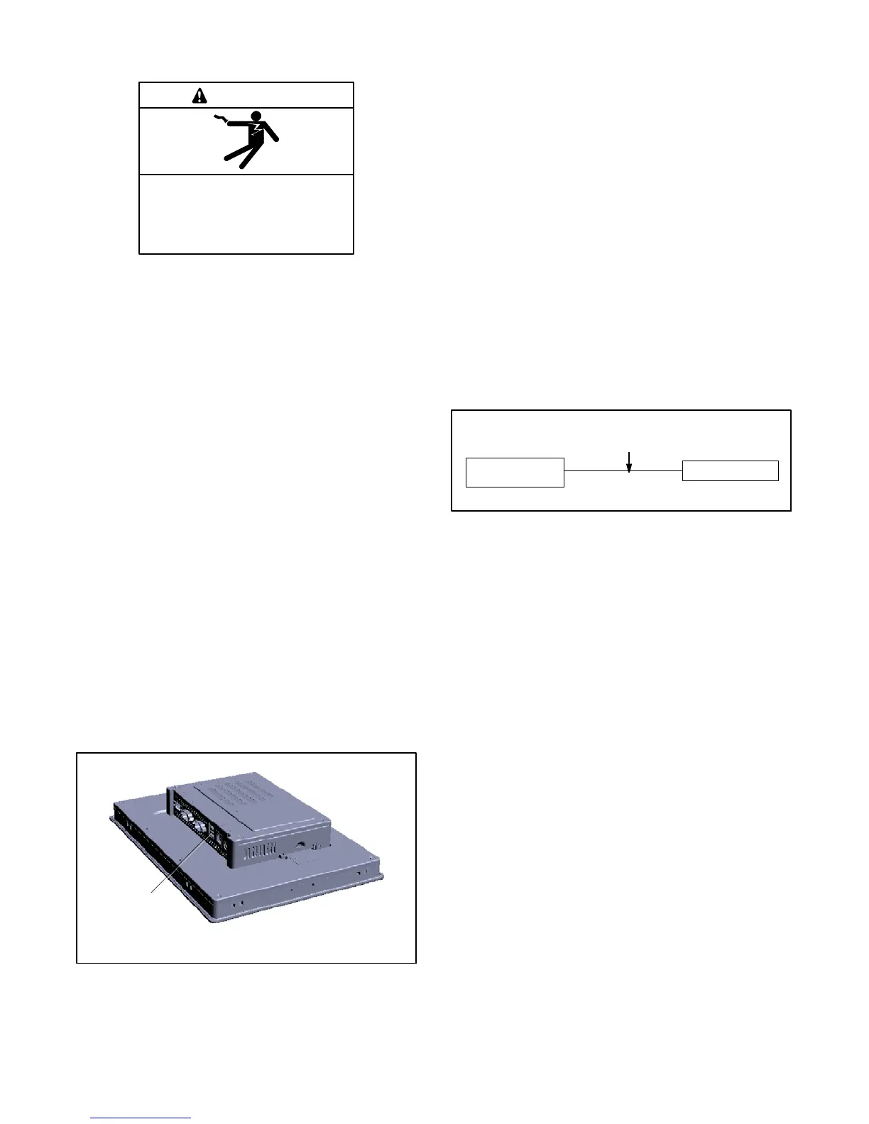
Mini USB Connectors for connection to a PC for
firmware updates or saving data files. Two USB ports
are located on the back of the controller’s
human-machine interface (HMI). See Figure 1-2. Lift
the hinged panel to access the USB ports.
Ethernet 3 port on the base module can be connected
to a personal computer or network to allow remote
monitoring using VNC.
Additional input and output connections are available
with optional module kits. See Section 5 for accessory
connection details.
1. USB Ports
1
Figure 1-2 USB Ports (back of HMI)
1.3.2 Modbus Connections
Use RS-485 cable for Modbus RTU connections.
Belden #9841 or equivalent shielded, twisted-pair cable
is recommended. See Figure 1-3. See the generator
set wiring diagram for the Modbus connection location
on TB10.
The controller also supports Modbus TCP over
Ethernet. Connect to the RJ45 port labeled Ethernet 3
on the controller’s base module.
The controller communicates using Modbusr as a slave
connection with the Modbusr master initiating the
communication. The controller seeks the system and
alternator parameters and diagnostic information then
responds back to the Modbusr master.
Note: Only one Modbusr master can be connected to
the controller. Examples include the remote
serial annunciator and switchgear applications.
Generator Set
Controller
Modbusr Master
RS-485
up to 1220 m (4000 ft.)
Figure 1-3 Modbusr Connections
 Loading...

