.
ATTACHMENTS, OPTIONS
HANDLING REMOTE POSITIONER
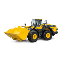
METHOD OF SETTING REMOTE POSITIONER STOP POSITION
1.
When RAISE stop display lamp (1) is lighted up, operate the
boom lever to raise the lift arm to the desired height (above
horizontal), then return the control lever to HOLD and press
RAISE position set switch (2).
RAISE stop display lamp (1) will go out and RAISE set pilot
lamp (3) will flash for 2.5 seconds.
When RAISE set pilot lamp (3) goes out and RAISE stop
display lamp (1) lights up, the RAISE stop position is recorded
in memory and the setting is complete.
2.
When LOWER stop display lamp (4) is lighted up, operate the
boom lever to lower the lift arm to the desired height (above
horizontal), then return the control lever to HOLD and press
LOWER position set switch (5).
LOWER stop display lamp (4) will go out and LOWER set pilot
lamp (6) will flash for 2.5 seconds.
When LOWER set pilot lamp (6) goes out and LOWER stop
display lamp (4) lights up, the LOWER stop position is
recorded in memory and the setting is complete.
SENSOR ADJUSTMENT FUNCTION
This function offsets the error caused by the mounting of the potentiometer and makes it possible to detect the
correct position data for the work equipment.
Always carry out this function when replacing the controller potentiometer or work equipment.
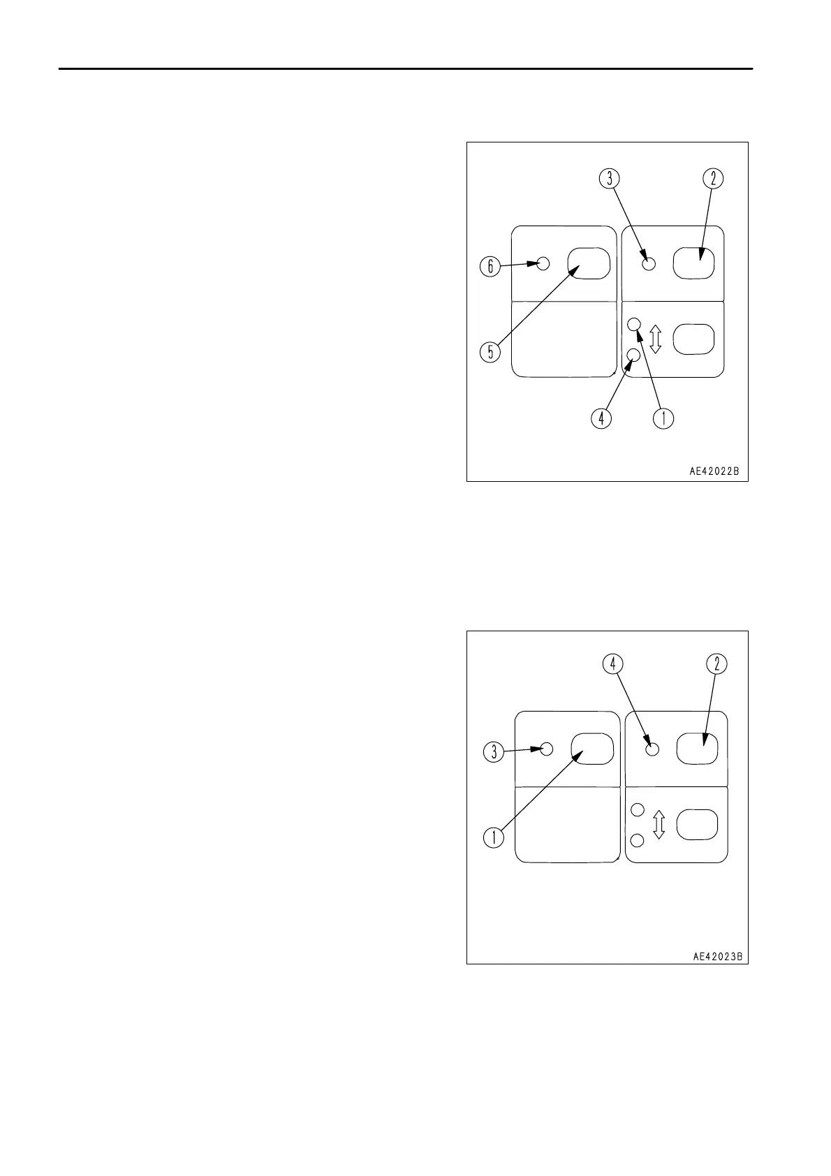
SENSOR ADJUSTMENT METHOD
1.
Set the work equipment to the lift arm top end position.
2. Keep LOWER position set switch (1) and RAISE position set
switch (2) pressed at the same time for at least 3 seconds.
When LOWER set pilot lamp (3) and RAISE set pilot lamp (4)
light up, release the switches and set to the sensor adjustment
mode.
3.
The LOWER set pilot lamp (3) and RAISE set pilot lamp (4)
light up for 2 seconds, and when both lamps go out, the offset
is recorded in memory.
4.
If the lamps flash in Step 3, the potentiometer output is not
within the offset range, so adjust the potentiometer mount.
Adjustment can be carried out at the posture in Step 1.
REMARK
After adjustment each potentiometer,always carry out Steps 1 and
2 again, and check that the condition in Step 3 is correct (the set
lamps light up for 2 seconds and then go out).
ADJUSTING REMOTE POSITIONER
When the lift arm has been removed or the setting does not work efficiently, please contact your Komatsu distributor
for adjustment.
6 - 14

 Loading...