S.l
ENGINE
GI700·GI800·GI900·G2000
WSM.l0831
B129F020
(3)
Alignment
Mark
(4)
TC
Mark
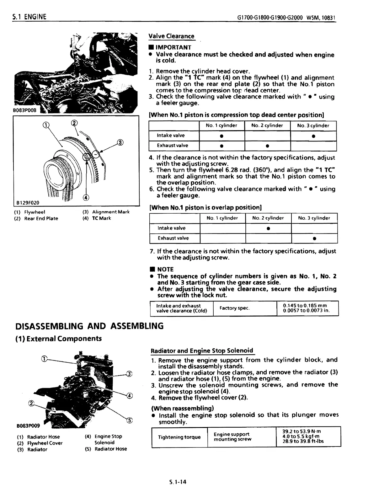
Valve Clearance
•
IMPORTANT
• Valve clearance must be checked and adjusted
when
engine
is cold.
1.
Remove
the
cylinder head cover.
2.
Align
the "1
lC"
mark (4)
on
the
flywheel (1) and alignment
mark
(3)
on
the
rear end
plate
(2)
so
that
the
No.1
piston
comes
to
the
compression
top
tiead center.
3.
Check the
following
valve clearance marked
with"
• • using
a feeler gauge.
[When
No.1
piston
is
compression
top
dead center position]
No.1 cylinder
No.2
cylinder
No.3
cylinder
Intake
valve
•
•
Exhaust valve
•
•
4.
If
the
clearance
is
not
within
the
factory specifications. adjust
with
the
adjusting screw.
S.
Then turn
the
flywheel 6.28 rad. (360°). and
align
the
"1 TC"
mark
and
alignment
mark
so
that
the
No.1
piston comes
to
the
overlap position.
6.
Check
the
following
valve clearance marked
with"
• using
If
a feeler gauge.
[When
No.1
piston is overlap position]
NO.1 cylinder
No.2
cylinder
NO.3
cylinder
Intake
valve
•
Exhaust valve
•
7.
If
the
clearance
is
not
within
the
factory specifications. adjust
with
the adjusting screw .
•
NOTE
• The sequence
of
cylinder numbers is given
as
No.1.
No.2
and
No.3
starting
from
the
gear
case
side .
•
After
adjusting
the
valve clearance. secure
the
adjusting
screw
wIth
the
lock nut.
Intake
and exhaust
0.145toO.185
mm
Factory spec.
valve clearance (Cold)
0.0057
too.oon
in.
(1) Flywheel
(2) Rear End Plate
DISASSEMBLING AND ASSEMBLING
(1) External Components
Radiator and Engine Stop Solenoid
1.
Remove
the
engine support
from
the
cylinder
block.
and
install the disassembly stands.
2.
loosen
the
radiator hose clamps. and remove
the
radiator
(3)
and radiator hose (1).
(S)
from
the
engine.
3.
Unscrew
the
solenoid
mounting
screws,
and
remove
the
engine stop solenoid (4).
4. Remove
the
flywheel cover (2).
(When reassembling)
• Install the engine stop solenoid
so
that
its
plunger
moves
smoothly.
(4) Engine Stop
Solenoid
(5) Radiator Hose
Engine
support
39.2
to
53.9 N·m
Tightening
torque
4.0
to
5.5
kt·m
mounting
screw
28.9
to
39.
ft·lbs
(1) Radiator Hose
(2) Flywheel Cover
(3) Radiator
5.1-14
 Loading...