II-149
WSM Minor Change II Service Engineering Section
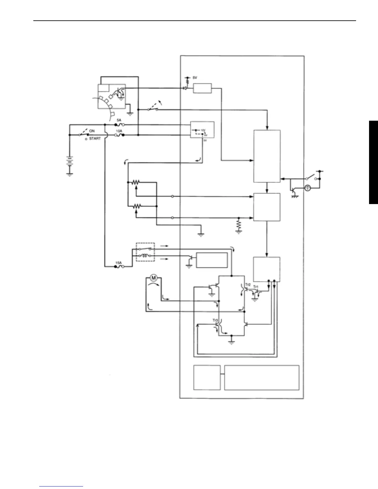
6. AI motor normal-turn circuit
Behavior:
1. The acceleration sensor signal and governor sensor signal are fed to the motor position control cir-
cuit.
2. The motor normal/reverse-turn circuit serves to select the AI motor turning direction based on the
lever position by the operator.
3. When the normal turn is selected as shown in the figure, the base current flows to the transistor Tr1.
Now the battery current flows for running the AI motor in the normal direction.
AI SW
Motor position
Acceleration sensor
Governor sensor
Acceleration cable
AI motor normal turn
Error detection
LCD
Output
Normal
Motor normal/
Governor position signal
Accelerator level position signal
Engine speed signal
AI pressure switch signal
Speed
Voltage change
AI controller unit
Engine speed sensor
Power
AI pressure
OFF by operating
detection
control circuit
the lever
switch OFF
reverse-turn
circuit
setting circuit
Normal
AI LED
AI effective with
engine started
AI control
timer circuit
Current motor
position
confirmed
AI relay
AI motor
return circuit

 Loading...