II - 39
WSM Minor Change II Service Engineering Section
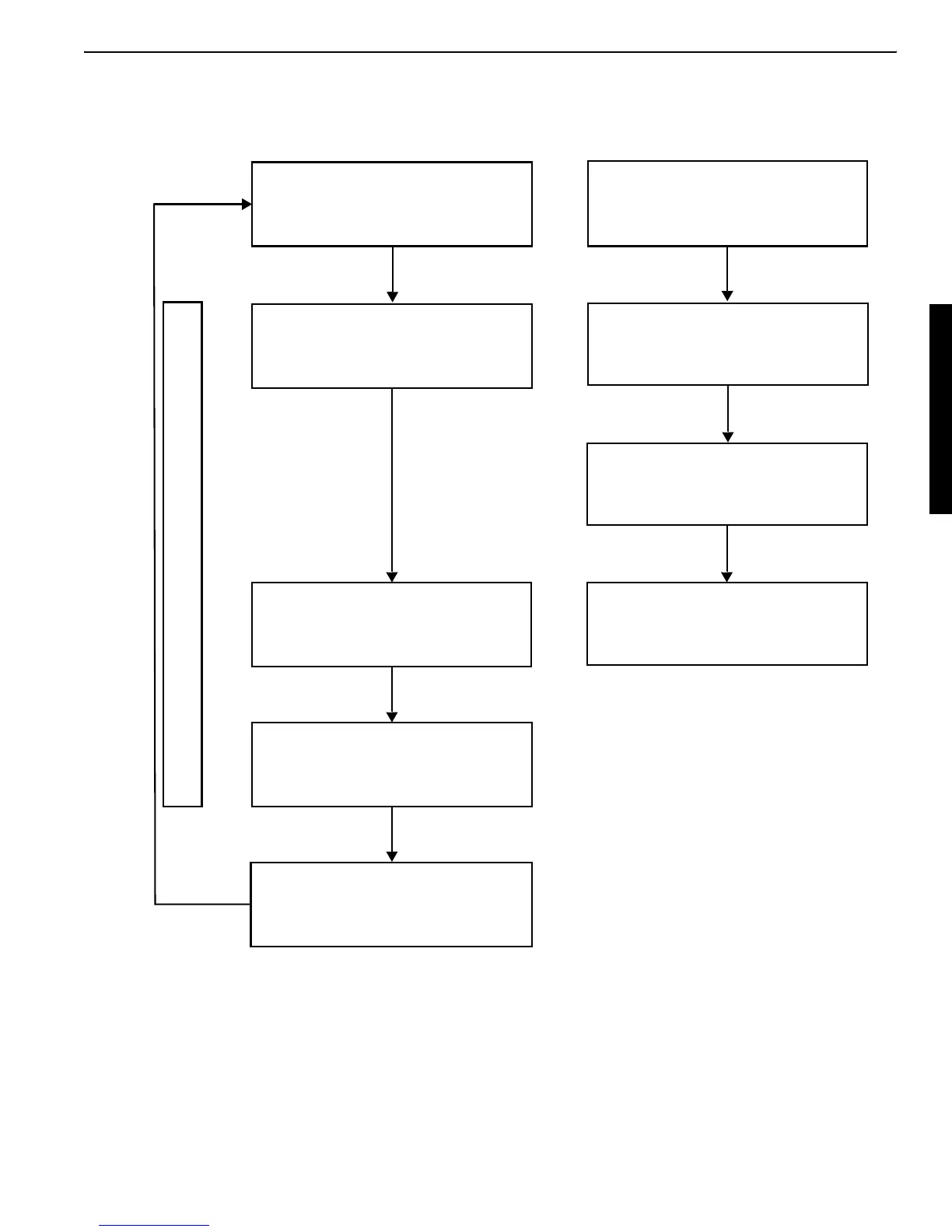
5. S/P valve initial set-up flow chart
For the right direction, enter the
knob's output voltage with the
engine at maximum rpm.
Visually make sure that the cylinder has started moving.
Controller
PWM current is
The proportional control solenoid
valve spool starts shifting.
The main control valve
spool starts shifting.
The thumb cylinder starts moving.
When the thumb cylinder starts
moving, press the service port
button on the panel.
Now the controller's PWM output cur-
rent has been set so that the thumb
cylinder starts moving at a preset
knob position (an input at maximum
rpm). This cylinder behavior occurs
at any engine speed.
Precisely speaking, controller’s out-
put current is the same at a preset
knob position.
Therefore, the solenoid force of the
S/P valve and the secondary pailot
pressure are identical.
So spool shift amount of the main
control value section is the same.
But as the main pump delivery rate
varies and so thumb cylinder’s start-
ing point varies according to the
engine speed to same extent.
Then why do the start-up setting at
max. engine speed?
For safety.
Setting complete.
Do the same for the left direction.
Enter the start-point output volt-
age in the controller.
outputted.
<Machine’s operation cycle> <Operator’s action>
 Loading...