II - 53
WSM Minor Change II Service Engineering Section
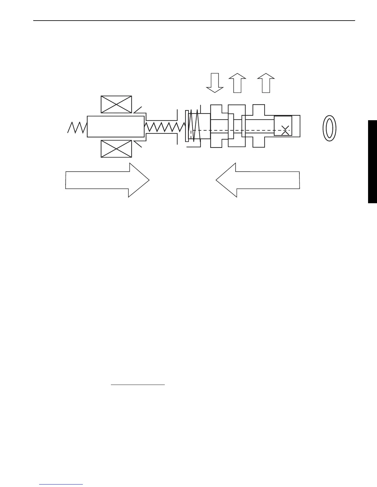
3. Function theory
Behavior of proportional valve
Behavior of solenoid proportional valve
Definitions of values
F
sol
: Solenoid magnetic force generated according to current
F
sol
= C1 x I (C1 and I are solenoid's intrinsic constant and current, respectively.)
F
sp1
: Solenoid's spring load
F
sp2
: Valve's spring load (constant during pressure control)
F
p
: Pressure applied by setup area difference
F
p
= A x Pa (A and Pa are setup area difference and pressure at port A, respectively.)
P: Primary pilot pressure from the pilot pump controlled by the unload relief valve
P
a
: Secondary pilot pressure to control the main control valve spool
Balance of forces
The balance of forces for the valve spool (see above) is expressed like this.
F
sol
+ F
sp1
= P
a
A + F
sp2
When the left term is greater, the spool moves rightward and ports P and A open one after the
other.
When the right term is greater, the spool moves leftward and ports A and P open one after the
other.
The above expression is rearranged as follows.
F
sol
+ F
sp1
- F
sp2
= P
a
A
Balance of proportional valve forces
Proportional solenoid
magnetic force
Reducing valve spool
hydraulic pressure force
P
a
PA T
sp1
sp2
Transfer
spring
A
Pressure receiving
area difference
F
sol
+ F
sp1
- F
sp2
A
P
a
=
 Loading...