II - 85
WSM Minor Change II Service Engineering Section
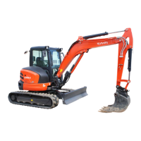
g. Travel motor: KX91-3S: PP-version
In this minor change, KX91-3S, U35S and U35-3S shockless valve spool has been deleted from the
travel motor. Still Kubota’s engineering has achieved the improved feeling at start-up and stop. Here
are the explanation in detail how done.
Improvement of start-up and stop feeling
1. Market demand to the travel motor
1) In-shoe type motor Wheel type motor
2) High speed
Hi-Low speed change structure
3) Traveling feeling
Shockless relief valve
Shockless spool
Anti-void valve
2. Counterbalance mechanism
1) At start-up and while traveling
Fig. 1 shows the circuit diagram when the
motor gets started and keeps running. The
hydraulic oil from the pump at start of the
motor is introduced to port P1. The hydrau-
lic oil flows through the check valve L to
keep the motor running. The hydraulic oil at
port P1 passes through the orifice L to act
against the end of the spool. The spool then
moves to the right against the force of
spring R. The return oil from the motor flows
through the variable orifice of the spool and
port P2, and back into the tank. When the
return oil passes via the spool's variable ori-
fice, a back pressure occurs at port M2. If
the counterbalance spool is slow in motion,
therefore, a higher-than-expected pressure
is applied at port M2 and you may feel a jolt
at the start of the machine.
When the motor stops and the control valve
gets back to neutral, the hydraulic oil from
the pump is cut off and the pressures at
ports P1 and P2 become the same as
shown in Fig. 1. Then, the spool is affected
by the force of spring R and comes back
from the state in Fig. 1 to that in Fig. 2. At
this time, the outlet port M2 is gradually
throttled by the variable orifice. On the other
hand, the motor keeps in motion by the iner-
tia force. This produces a brake pressure at
port M2, by which the motor gradually slows
down and comes to a stop. If the pressure
at M2 would rise violently, the motor would
come to a sudden stop and you would feel a
jolt at the stop.
(1) Pump
(2) Orifice L
(3) Check valve L
(4) Variable orifice part
(5) Counterbalance spool
(6) Spring R
(7) Control valve
(8) Tank
Fig.1 At start-up and while traveling
(4)
(5)
(6)
(3)
(1)
(2)
(7)
(8)
 Loading...