THREE-POINT HITCH & DRAWBAR44
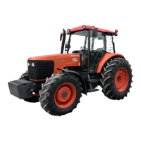
BTop Link
To avoid personal injury:
A When extending the top link, do not exceed the
groove on the top link thread, or the top link will
come apart and the 3-point equipment may fall.
1. Adjust the angle of the implement to the desired
position by shortening or lengthening the top link.
2. The proper length of the top link varies according to
the type of implement being used.
A The length of the screw at both ends of the top link
must be the same always.
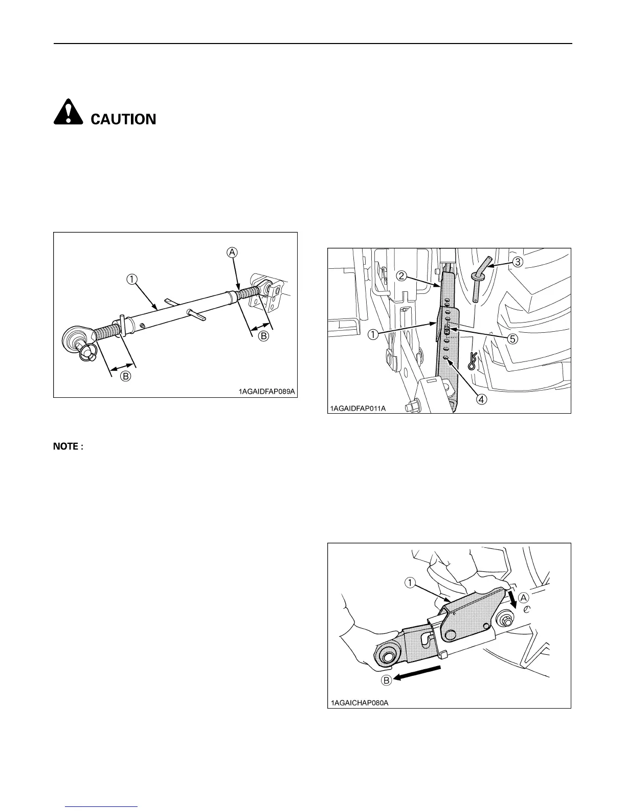
BTelescopic Stabilizers
Adjust the telescopic stabilizers to control horizontal sway
of the implement. Select the proper set of holes by
referring to the "Hydraulic Control Unit Use Reference
Chart" in "REMOTE HYDRAULIC CONTROL SYSTEM"
in "HYDRAULIC UNIT" section.
After aligning satisfactorily, insert the set-pin through any
one of the 5 holes on the outer tube that align with one of
the holes on the inner bar, both stabilizers will be locked.
If the set-pin is inserted through the slot to engage one of
the holes on the inner bar, a limited degree of sway will be
permitted.
BTelescopic Lower Links
To attach an implement, follow the instructions below:
1. Push the levers, pull out the lower link ends, and
attach to the implement.
2. Back up the tractor slightly to make sure the lower links
are pushed in securely.
(1) Top link (A) "GROOVE"
(B) "Length of the screw"
(1) Outer tube
(2) Inner bar
(3) Set-pin
(4) Hole
(5) Slot
(1) Lever (A) "PUSH"
(B) "PULL OUT"

 Loading...