49HYDRAULIC UNIT
BFlow Control Valve (option)
The optional flow control valve may be added for the
following purposes.
1. To operate within limits, the remote control valve (2)
above the flow control valve (3) and the 3-point hitch
at the same time without one affecting the other.
2. To operate within limits, the remote control valve (2)
above the flow control valve (3) and the other remote
control valve (1) at the same time without one affecting
the other. Activating the remote control valve (1) will
interrupt the operation of the 3-point hitch.
3. To maintain within limits, the constant speed of an
attachment (hydraulic motor RPM, for example) when
connected to the remote control valve (2) above the
flow control valve (3).
A At slower engine speeds the total hydraulic flow rate
may be inadequate for simultaneous operation of the
remote control valve (2) and the 3-point hitch or the
remote control valve (1), or operation of an attachment
connected to the remote control valves (1)(2). Under
these conditions, the engine speed must be increased
to provide additional hydraulic flow.
BAdjusting the flow rate
To avoid the possibility of personal injury be
aware of the following when making adjustments:
A The 3-point hitch operation is influenced by the
combination of the adjustment of the flow
control valve and the engine speed.
A The 3-point hitch may raise slowly or not at all
at low engine RPM.
A The 3-point hitch may raise suddenly if engine
RPM is increased, or, flow control adjustment
is changed.
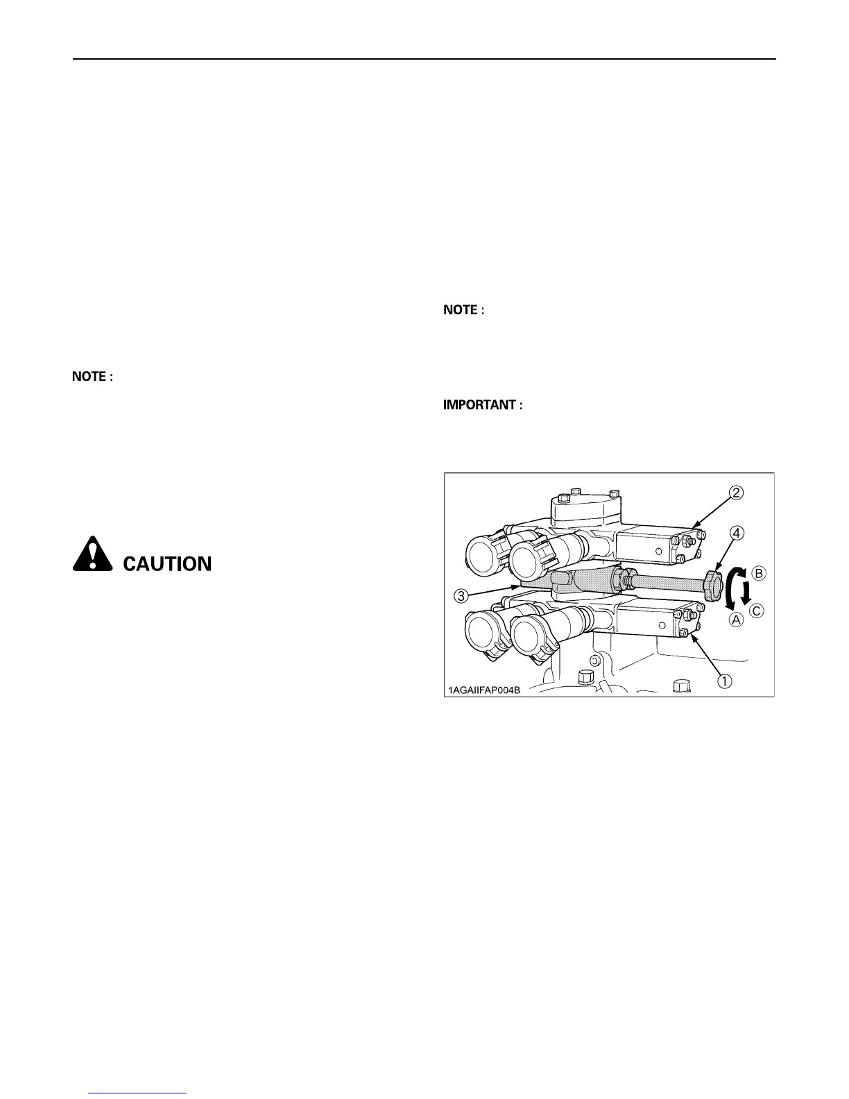
Refer to the illustration below.
1. The flow rate for the remote control valve (2), located
on above the flow control valve (3), can be adjusted.
2. Turn the flow control knob (4) counterclockwise (A),
and the flow rate for the remote control valve (2)
increases. A clockwise turn (B) of the knob causes the
flow to decrease. If the knob is turned all the way (C),
there will be no flow.
3. To adjust the flow rate, set the engine speed to the
operating RPM, turn the flow control knob once all the
way clockwise (C), and then turn it gradually
counterclockwise until a required flow rate is reached.
A Full adjustment of the valve will occur in approximately
1 1/2 revolutions of the flow control knob. Turning the
flow control knob beyond this point will have no affect
on the flow rate.
A When there is no need to adjust the flow rate, turn the
flow control knob all the way counterclockwise and
keep it in this position.
(1) Remote control valve (1)
(2) Remote control valve (2)
(3) Flow control valve
(4) Flow control knob
(A) "INCREASE"
(B) "DECREASE"
(C) "STOP"

 Loading...