ELECTRICAL SYSTEM
L3540-II, L4240-II, L5040-II, L5240-II, L5740-II , WSM
9-S70
[12] OTHERS
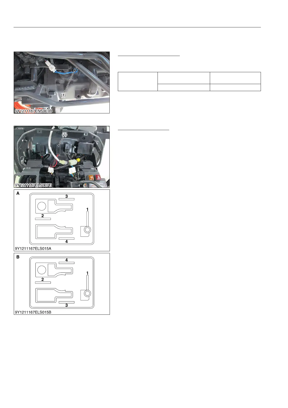
(1) PTO Speed Change Switch (Manual Transmission Model)
PTO Speed Change Switch
1. Measure the resistance across the sensor terminals.
2. If the reference value is not indicated, the sensor is damaged.
9Y1211167ELS0093US0
(2) Electrical Outlet Relay
Electrical Outlet Relay
1) Connector Voltage
1. Turn the main switch off.
2. Disconnect the electrical outlet relay (1).
3. Measure the voltage across the terminal 1 (Positive) and
chassis (Negative).
4. If the voltage differs from the battery voltage, the wiring harness
is faulty.
5. Turn the main switch on.
6. Measure the voltage across the terminal 3 (Positive) and
chassis (Negative).
7. If the voltage differs from the battery voltage, the wiring harness
is faulty.
2) Electrical Outlet Relay
1. Remove the electrical outlet relay.
2. Apply battery voltage across terminals 1 and 2, and check for
continuity across terminals 3 and 4.
3. If continuity is not established across terminal 3 and 4, replace
the electrical outlet relay.
9Y1211167ELS0094US0
Resistance
(Across sensor
terminals)
When the switch is
released
Infinity
When the switch is pushed 0 Ω
(1) Electrical Outlet Relay A: Connector of Wire Harness Side
B: Connector of Electrical Outlet
Relay
 Loading...


