Basic units in the power range 3 ... 11 kW
Mounting in ”cold plate” technique
5
Basic device installation
5.4
5.4.3
L
5.4-5
EDS82EV903-1.0-11/2002
M6
4Nm
35 lbin
c
f
a1
b1
b
a
d
c1
b2
e
8200vecxxx
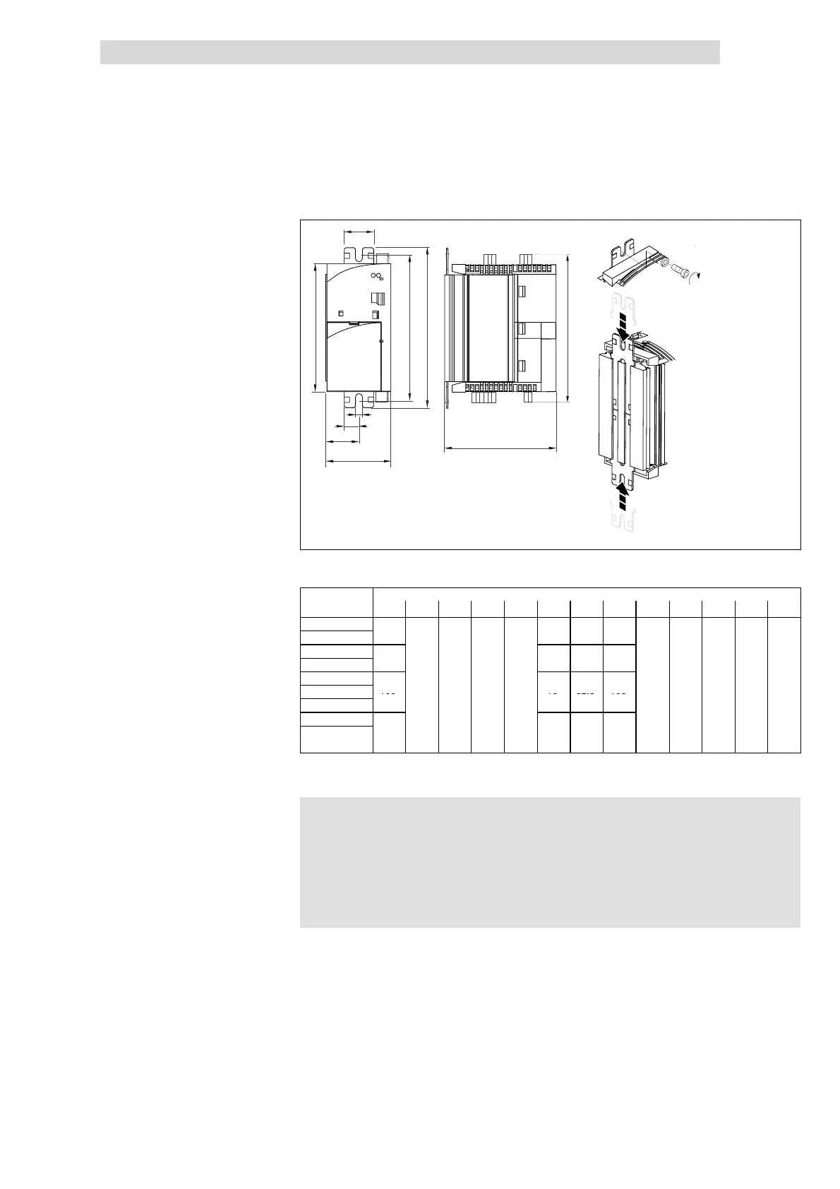
Fig. 5.4-4 Dimensions for mounting in ”cold plate” technique 3 ... 11 kW
Dimensions [mm]
8200 vector a b b1 b2 b3 c1 c2 c3 c4 d1 d2 e g
E82CV302K2C
E82CV402K2C
.5
E82CV552K2C
E82CV752K2C
5
.5
E82CV302K4C
E82CV402K4C
100
7
19 62.5 103
5
E82CV552K4C
eep
E82CV752K4C
E82CV113K4C
125 22 84.5 128
)
))
) Note!
l Apply heat-conducting paste before you bolt together the
cooler and the heatsink to keep the thermal resistance as low
as possible.
l The quantity of heat-conducting paste supplied in the delivery
package is sufficient for approx. 1000 cm
2
.
1. Slide the mounting rails into the heatsink from the top and from the bottom
2. Clean the area of contact between the heatsink and the cooler with
methylated spirits.
3. Apply a thin layer of heat-conducting paste.
4. Bolt the drive controller onto the cooler using two screws.
8200 vector 3 ... 11 kW
Mounting
 Loading...