Basic units in the power range 0.25 ... 2.2 kW
Terminal assignment - Application I/ O E82ZAFA
7
Extensions for automation
7.2
7.2.4
L
7.2-12
EDS82EV903-1.0-11/2002
X3.1/
1U/2U
Temperature erro r (0...+60°C) for level (ref. t o current value):
1I/2I
• 0 ... +5 V:
• 0 ... +10 V:
• -10V... +10V:
• 0/4 ... +20 mA:
1%
0.6 %
0.6 %
0.6 %
Linearity fault: ± 0.5 %
A/D converter:
Resolution: 10 bit,
Error (ref. to limit value): 1 digit
≡ 0.1 %
Input resistance
: Voltage signal: > 50 k Ω, current signal: 250 Ω
X3.2/
62
63
Resolution: 10 bit
Linearity fault (ref. to current value):
±0.5 %
Temperature error (0...+60 °C): 0.6 %
Load capacity (0 ... +10 V): I
max
=2mA
Load resistance (0/4... 20 mA):
≤ 500 Ω
9 Load capacity: I
max
=5mA
X3.3/
A1
A2
Load capacity:
• I
max
= 10 mA, with internal supply
• I
max
= 50 mA, with external supply
A4 Load capacity: I
max
=8mA
f = 50 Hz ...10 kHz
20 Load capacity: Σ I
max
=60mA
28
E1
1)
Input resistance: 3.2 kΩ
E2
1)
E3
E4
1=HI
H (+12 ... +30
), PL
level, HTL
E5
=
... +
,
eve
,
E6
1)
or frequency input 0 ... 100 kHz, single or two track, configuration via C0425
9
1I
2U
1U
2I 62 63
+5 V
AIN2 AOUT2AIN1 AOUT1
1U
9
7
0 … +5 V
1k … 10k
GND
A2A1 7 7 A4 20 28
E1
E2 E3 E4 E5 E6
59
GND
+20 V
DIGOUT2 DFOUT1DIGOUT1
X3.1
X3.2
X3.3
9
1I
2U
1U
2I 62 63
+5 V
AIN2 AOUT2AIN1 AOUT1
1U
9
7
0 … +5 V
1k … 10k
GND
A2A1 7 7 A4 20 28
E1
E2 E3 E4 E5 E6
59
GND
+20 V
+
_
DIGOUT2 DFOUT1DIGOUT1
24Vext.
(+12VDC-0% ... +30VDC+0%,
max. 200 mA)
X3.1
X3.2
X3.3
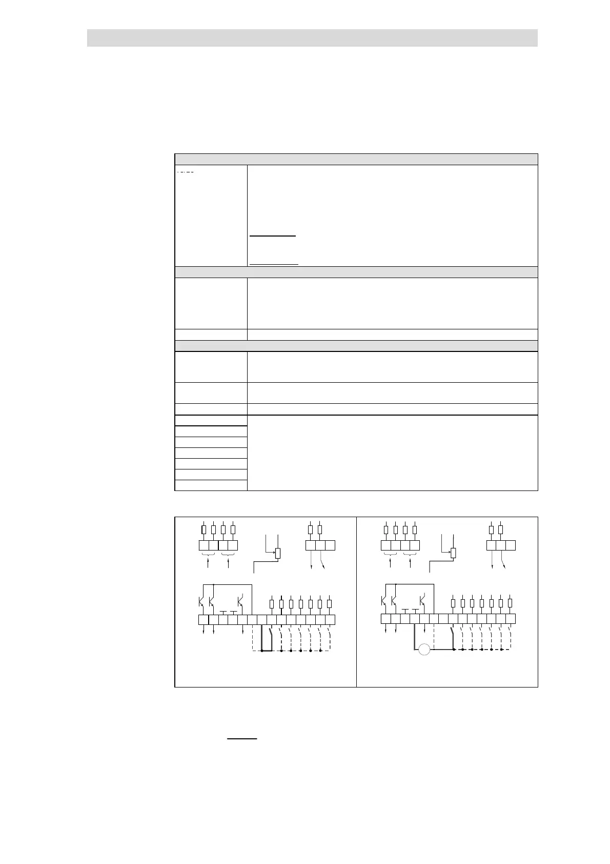
E82ZAFA001 E82ZAFA002
Fig. 7.2-8 Wiring at internal /external supply
internal voltage source X3/20 (+20 V DC, max. 60 mA)
external voltage source + 24 V DC (+12 V DC - 0 % ... +30 V DC + 0 %,
max. 200 mA)
The min. wiring requirements for operation
Technical data
Wiring
 Loading...