Basic units in the power range 0.25 ... 2.2 kW
Thermally separated mounting (push-through technique)
5
Basic device installation
5.3
5.3.2
L
5.3-3
EDS82EV903-1.0-11/2002
3.
3.
2.
1.
1.
4.
5.
E82DV_001
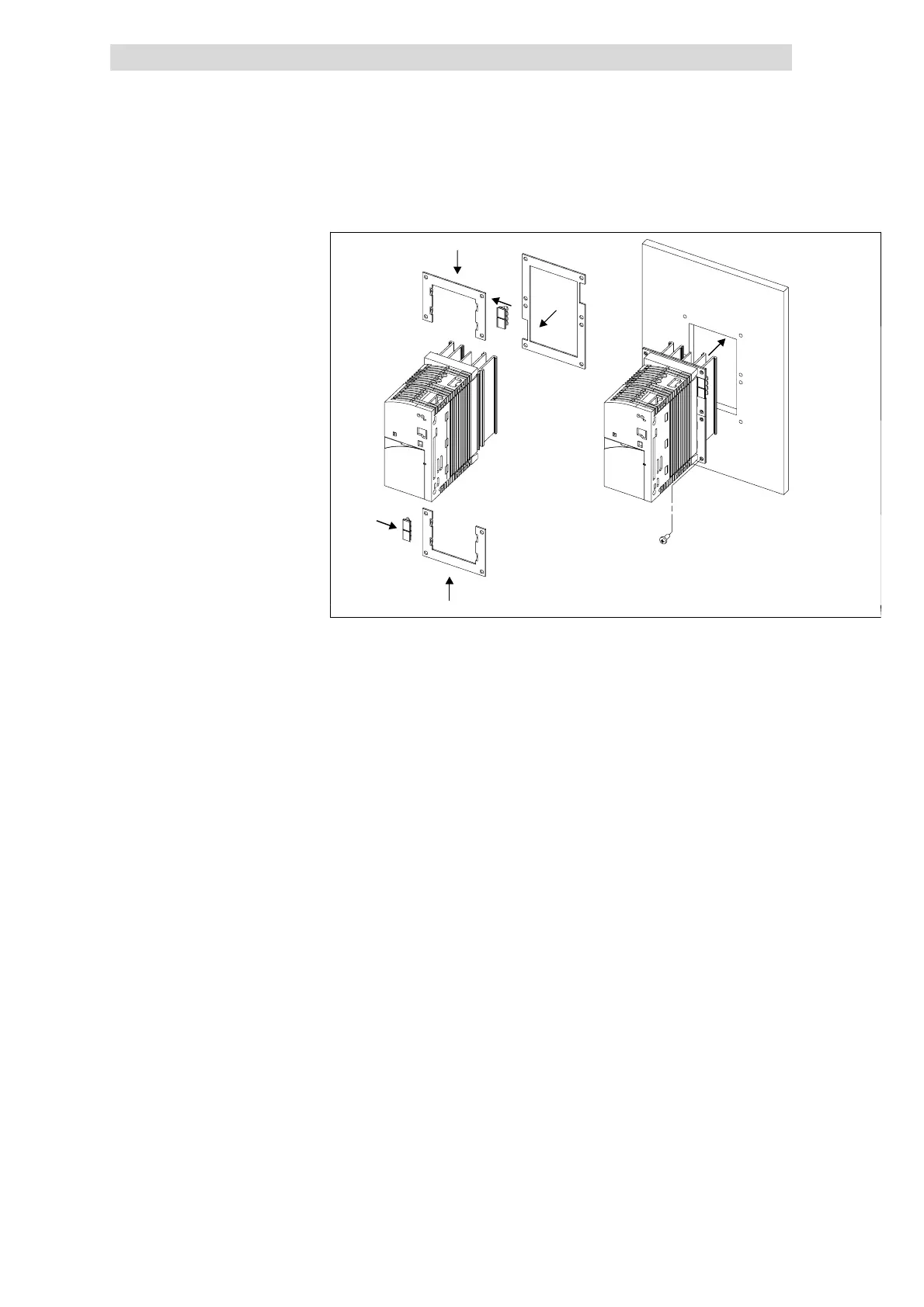
Fig. 5.3-3 Thermally separated mounting 0.25 ... 0.75 kW
1. Push in the fixing frames
2 Insert seal
3. Push the grounding terminals with the correct end onto the fixing frame:
– The contact springs must point to the rear panel of the control cabinet
– The cutouts of the seal determine the positions
4.
Insert the 8200 vector into the cutout
5. Fasten it with 8 M4x10 screws
Mounting
 Loading...