Basic units in the power range 45 ... 55 kW
Power connections
6
Basic unit wiring
6.7
6.7.2
L
6.7-5
EDS82EV903-1.0-11/2002
l
E.l.c.bs must only be installed between mains supply and controller.
l E.l.c.bs can trip incorrectly because of
– capacitive leakage currents of the cable shields during operation
(especially with long, shielded motor cables),
– simultaneous connection of several controllers to the mains supply,
– use of additional RFI filters.
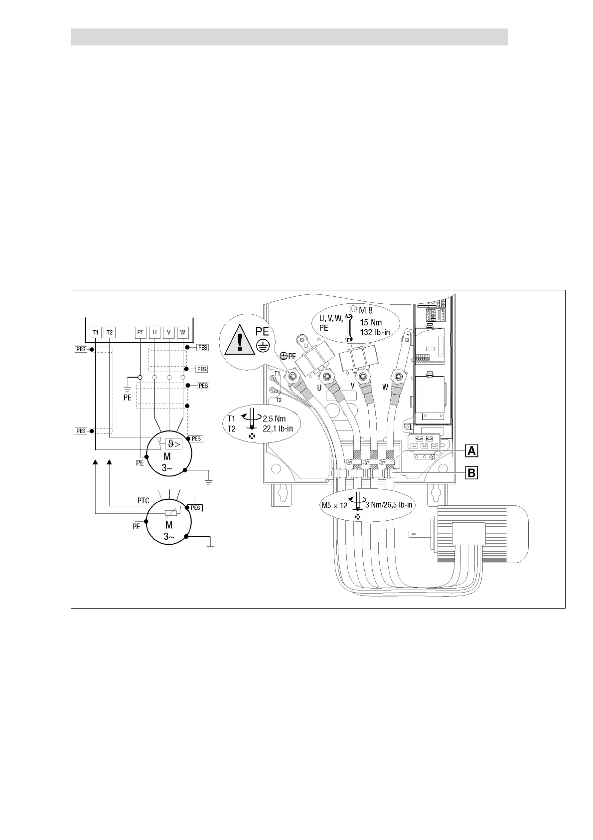
Motor connection
8200vec286
Fig. 6.7-3 Motor connection 45 ... 55 kW
0
Connect the shields of the motor cables with the shield clamp and screws M5
12 mm to the shield sheet.
1
Strain relief with cable ties.
Use low-capacity motor cables! (Core/core ≤ 190 pF/m, core/shield ≤ 320
pF/m)
Use short motor cables if possible!
PES
HF-shield end by PE connection via shield clamp.
T1,
T2
Connection terminals of motor temperature monitoring with PTC thermistor or
thermal contact (NC contact).
Route a separate cable (shielded) to X2/T1 and X2/T2 for the motor
temperature monitoring.
Activate the motor temperature monitoring under C0119 (e. g. C 0119 = 1)!
Route the control and mains cables separately from the motor cable!
Please observe the following
when using e.l.c.bs: