Basic units in the power range 75 ... 90 kW
Connection of relay outputs K 1 and K2
6
Basic unit wiring
6.8
6.8.3
L
6.8-6
EDS82EV903-1.0-11/2002
Cable cross-sections U, V, W, PE
8200 vector mm
2
AWG
E82EV753K4B 70 2/0
E82EV903K4B 95 3/0
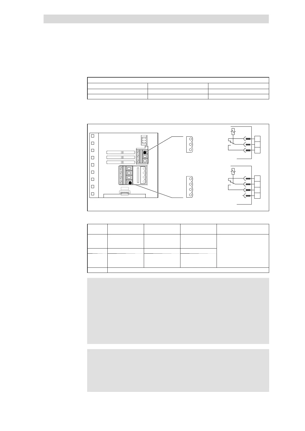
6.8.3 Connection of relay outputs K1 and K2
K14
K1
K2
K12
K11
K24
nc
K11
K21
K12
K22
X1.2
X1.3
K14
K24
nc
K22
K21
8200vec261
Fig. 6.8-4 Relay connections K1 and K2
Function Relay position set Message
(Lenze setting)
Technical data
X1.2/K11 Relay output
normally-closed
contact
open TRIP
X1.2/K12 Mid position contact
5
X1.2/K14 Relay output -
normally-open
contact
closed TRIP
...
.
PES HF-shield end by PE connection through shield bracket.
)
))
) Note!
l For switching the control signals use shielded cables and
establish an HF shield termination by PE connection.
l For mains potential switching unshielded cables are sufficient.
l The service life of the relay depends on the type of load (ohmic,
inductive or capacitive) and the value of the switching capacity.
l The output message can be changed under C0008 or C0415/1.
(
((
( Stop!
If you control a holding brake at the motor with the relay output, a
spark suppressor must be used in case of DC switching:
l Universal spark suppressor for 24 V DC brake,
l 6-pole Lenze brake rectifier for 180 V/205 V DC brake.
Cable cross-sections
Relay K1
 Loading...