Basics for wiring according to EMC
Shielding
6
Basic unit wiring
6.3
6.3.2
L
6.3-2
EDS82EV903-1.0-11/2002
6.3.2 Shielding
The quality of shielding is determined by:
l a good shield connection
– a contact surface as large as possible
l a low resistance:
– Only use shields with tin-plated or nickel-plated copper braids!
l Always connect the shield to the conductive and grounded mounting plate
withasurfaceaslargeaspossibleviaaconductiveclamp.
l Connect the shield directly to the corresponding device shield sheet.
l Do not only connect the shield to the cable clamp.
l The unshielded cable ends must be as short as possible.
l Terminals must be separated, minimum distance: 100 mm
l Minimum distance between the shield clamps for control cable and motor
cable: 50 mm
l If the motor cable must be interrupted due to chokes or terminals, the
unshielded cable must not be longer than 40 - max. 100 m ( depending on
the cable cross-section).
l If the motor cable must be interrupted due to contactors, switches or
terminals, these must be separated from the other components. (at least a
distance of 100 mm)
l In case of cable lengths up to 500 mm a second shield (shield connection)
is not required.
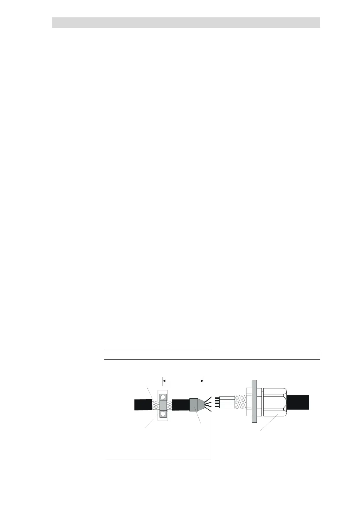
Motor cables Cable gland
Motor supply cable
max. 500mm
Extensive
contact of the
cable shiel
Braid
Heat-
shrinkable tube
Cable connector accordin
to EMC
for cable glands with high
degree of protection.
Cable gland
Fig. 6.3-1 Shielding of the motor cable
Requirements
Wiring technique
Motor cables
 Loading...