Basic units in the power range of 15 ... 90 kW
Terminal assignment - Application I/ O E82ZAFA
7
Extensions for automation
7.4
7.4.4
L
7.4-11
EDS82EV903-1.0-11/2002
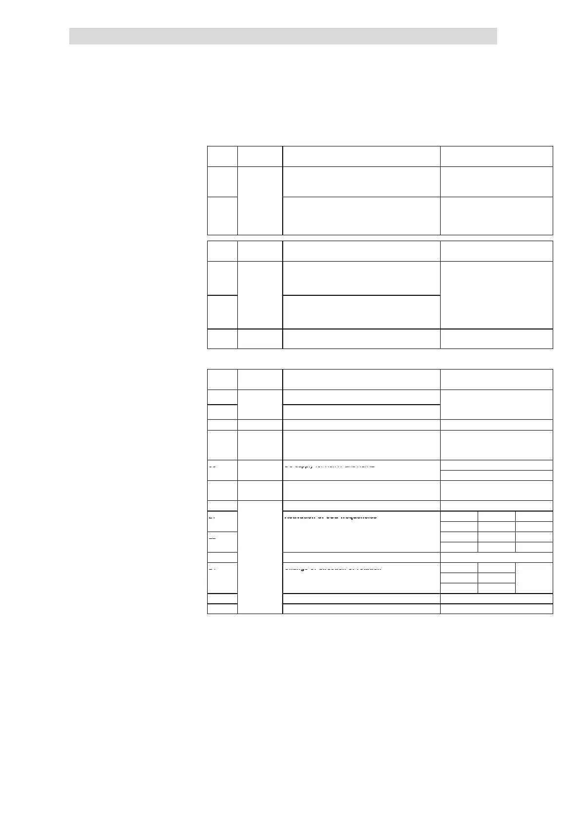
X3.1/ 28 Signal type Function Level
(Lenze setting, in bold print)
1U/2U Analog inputs Actual or setpoint inputs (master voltage)
0 ... +5 V
se
umper an
to c
ange range
... +
-10V...+10V
1I/2I Actual or setpoint inputs (master current)
Use jumper and C0034 t o change ra nge
0 ... +20 mA
+4 ... +20 mA
+4 ... +20 mA (open-circuit
monitored)
X3.2/ 29 Signal type Function
(Lenze setting, in bold print)
Level
(Lenze setting, in bold print)
62
Analog
outputs
Output frequency
Voltage output:
0 ... +6 V
0 ... +10 V
1)
63 Motor current
urrent output:
(0 ... +12 mA)
0 ... +20 mA
1)
4 ... +20 mA
9 - Internal, stabilised DC voltage supply for setpoint
potentiometer
+5.2 V
1)
Output level 0 ... + 10 V or 0 ... +20 mA: Adapt offset (C0422) and gain (C0420)
X3.3/ 29
Signal type Function Level
(Lenze setting, in bold print)
A1
Digital
Ready for operation
A2
ou
pu
s
not prefabricated
0
+20
at DC internal
0/+24 V at DC external
7 - GND, reference potential -
A4 Frequenc y
output
DC bus voltage HIGH:
+15 V...+24 V (HTL)
LOW: 0 V
59 - DC supply for X3/A1 and X3/A2
+20 V (internal, bridge to X3/20)
+24 V (external)
20 - Internal DC voltage supply for control of digital
inputs and output
+20 V ± 10 %
28 Controller inhibit (CINH) 1 = START
E1
2)
Activation of JOG frequencies
E1 E2
JOG1 = 20 Hz
JOG1 1 0
E2
2)
JOG2 = 30 Hz
JOG2 0 1
JOG3 = 40 Hz
JOG3 1 1
E3
Di
ital in
uts
DC-injection brake (DCB) 1=DCB
E4
Change of direction of rotation
E4
CW/CCW rotation
CW 0
CCW 1
E5 not prefabricated -
E6 not prefabricated -
2)
Optional frequency input 0 ... 100 kHz, single-tracked or double-tracked, configuration via C0425
Terminal assignment

 Loading...