Behaviour in the event of mains switching, mains failure or controller inhibit
Controlled deceleration after mains failure/mains disconnection
10
Function library
10.5
10.5.3
L
10.5-5
EDS82EV903-1.0-11/2002
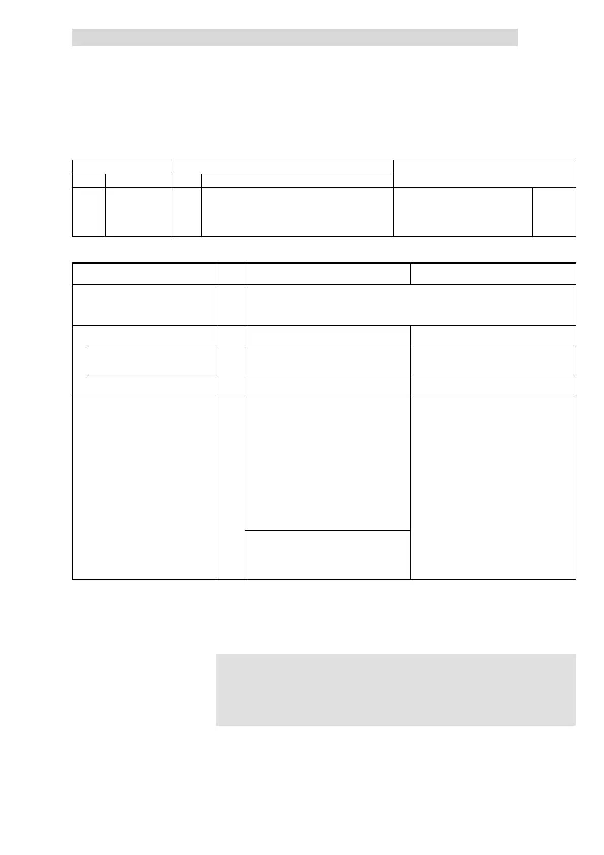
Codes for parameter setting
Code Possible settings IMPORTANT
No. Name Lenze Selection
C0988* DC-bus voltage
threshold for
DC-bus voltage
control
0 0
Parameter set
changeover via
DC-bus voltage
deactivated
{1 %} 200 • Changeover always between PAR1 nd
PAR2
• Parameter set changeover is not
possible via terminal, bus or PC if C988
>0!
^ 10.5-4
^ 10.7-8
Adjustment
Parameter Code Parameter set 1
(active in the event of mains failure)
Parameter set 2
(active in normal op eration)
Changeover threshold C0988 Set C0988 to approx. 10 % undervoltage:
AC 230 V
ð C0988 = 75 ... 85 %
AC 400 V
ð C0988 = 75 ... 85 %
AC 460 V
ð C0988 = 75 ... 98 %
Terminal configuration C0410 L ink C0410/4 (DCTRL1-QSP) with a digital input
(X3/E1 ... X3/E6).
Set terminal configuration for normal operation.
Quick stop (QSP) is active in normal
operation
Invert this input under C0411.
(Lenze setting = LOW active)
Link the digital input linked with DCTRL1-QSP in
parameter set 1 with DCTRL1-QSP (not inverted),
too, and connect the digital input.
No quick stop (QSP) in normal operation Do not use this input. Do not use the digital input linked with DCTRL1-QSP
in parameter set 1.
Deceleration time for quick stop (QSP) C0105 Without external brake resistor
The setting must ensure that the motor decelerates
to standstill in a controlled mode after mains swit ch
off:
1. Set the same value as in parameter set 2.
2. Switch off the mains voltage.
– Parameter set 1 is activated.
– Observe whether the controller indicates
“Overvoltage OU” during controlled
deceleration.
3. Repeat the controlled deceleration and reduce
C0105 until the controller i ndicates ”OU”.
4. Increase this value by approx. 20 % and use it as
final setting.
Set the QSP deceleration time required for this
application.
With external b rak e resistor
Select a sufficiently high external brake resistance.
1. Se t C0105 a s in parameter set 2.
2. Reduce C0105 until the required deceleration
time after mains switch-off is available.
The smoothest deceleration can be achieved by setting the max. limit of the
bandwidth set under C0988.
The current limit in generator mode must not be exceeded during controlled
deceleration.
)
))
) Note!
l Parameter set changeover via terminal, bus or PC is not
possible if C0988 > 0!
l C0988 is the same in all parameter sets.
Tip

 Loading...