 Loading...
Do you have a question about the Lenze E82MV752 and is the answer not in the manual?
| Input Voltage | 3-phase 380-480V AC |
|---|---|
| Output Current | 4.2 A |
| Protection Class | IP20 |
| Frequency Range | 50-60 Hz |
| Control Mode | Vector Control |
Defines symbols, warnings, and notation for clear understanding of manual content.
Explains pictographs and signal words used for dangers and important information.
Specifies the intended use and limitations for the 8200 motec frequency inverter and accessories.
Provides fundamental safety guidelines applicable to all Lenze drive and automation components.
Outlines safety and application guidelines specifically for Lenze motors.
Identifies potential dangers and risks associated with controller operation and handling.
Covers conformity, approvals, protection, EMC, and general operating parameters.
Details power, current, and voltage specifications for normal operating conditions.
Provides physical dimensions and weight specifications for the device and fan module.
Guides on installing the motec unit directly onto a motor or geared motor.
Instructions for mounting the 8200 motec unit onto a wall.
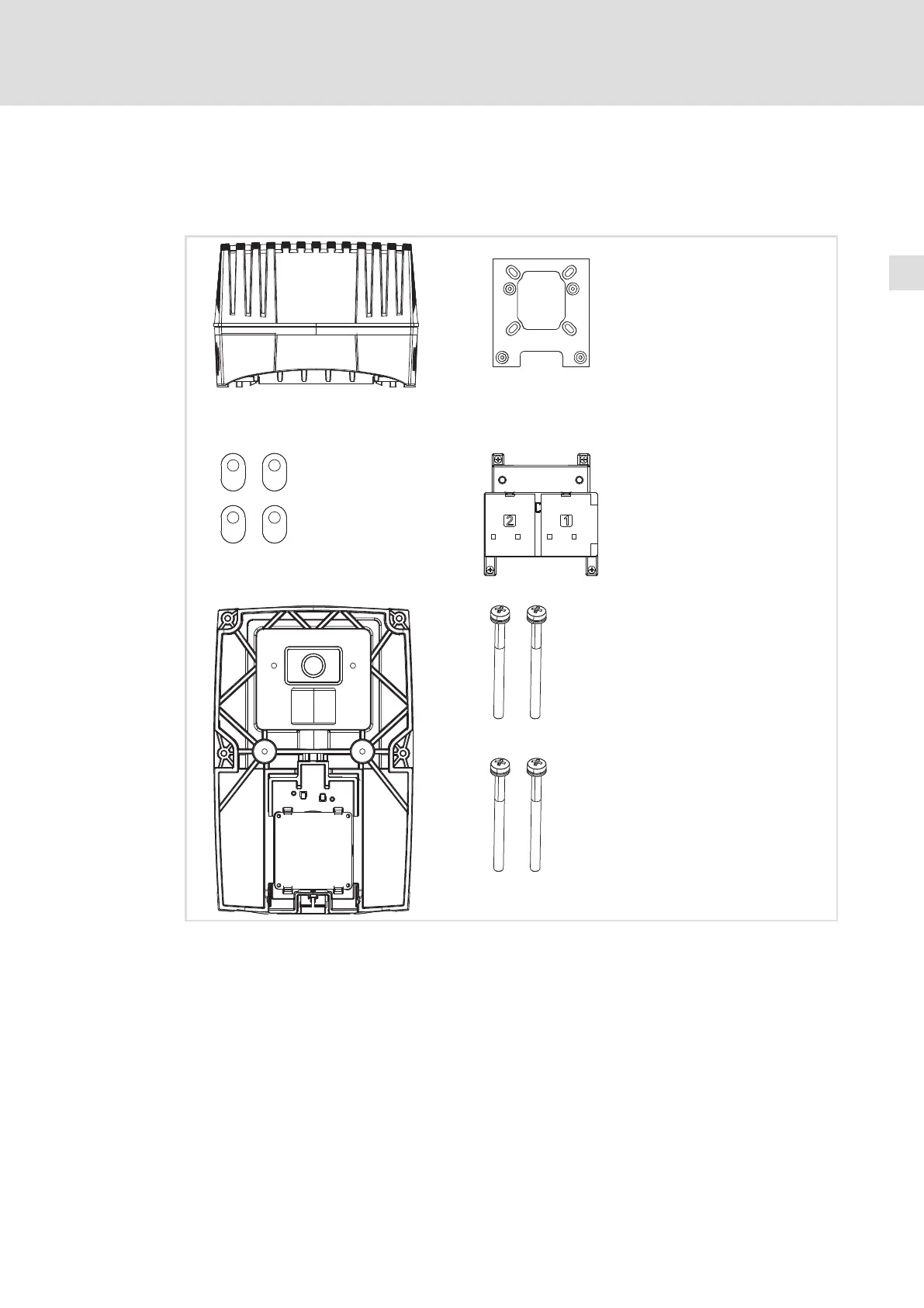
Details the process of mounting the motec onto a motor, including scope of supply and preparation.
Explains how to safely connect the device to the mains power supply, including fuses and cable sizes.
Describes how to connect the relay outputs for signaling or control purposes.
Details the connection of the digital switching output, specific to device version 152.
Step-by-step guide for installing optional function modules onto the motec.
Covers the final assembly of the motec, including with and without function modules.
Crucial checks and preparations before applying mains voltage to the controller.
Guides on choosing between V/f, Vector, and Sensorless torque control modes.
Instructions for configuring parameters using the E82ZBB diagnostic keypad.
Step-by-step guide for setting up the linear V/f control mode.
Step-by-step guide for setting up the vector control mode, including motor parameter identification.
Explains the meaning and usage of various parameter codes for configuration and operation.
Provides a systematic approach to diagnose and resolve operational issues and maloperations.
Lists and explains common fault codes and their causes/remedies.
Explains the meaning of the controller's status LEDs for diagnostics.
