Mechanical installation
Wall mounting
Wiring according to EMC (CE−typical drive system)
4
85
EDK82MV752 DE/EN/FR 7.2
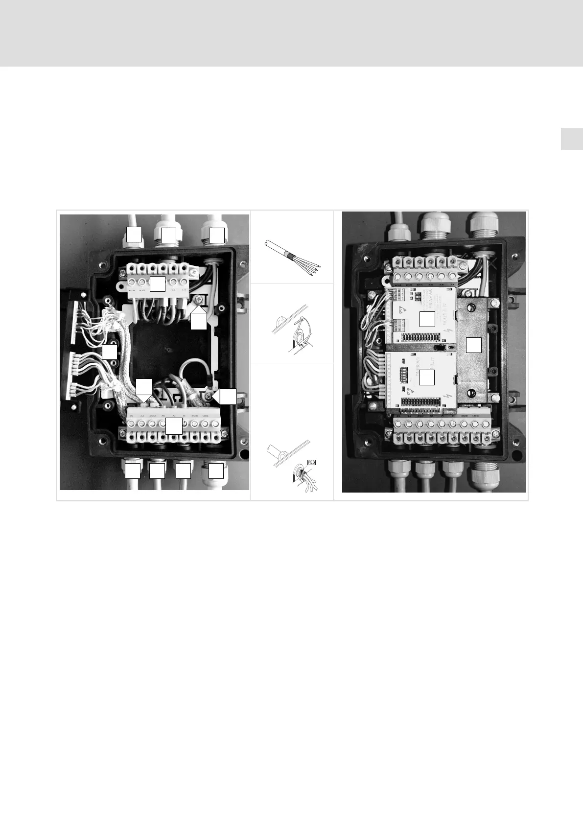
4.2.4 Wiring according to EMC (CE−typical drive system)
Conditions for trouble−free operation:
ƒ Except for the mains cable, use shielded cables only.
ƒ The shield must be carefully connected to PE (see below).
ƒ Separate control and mains cables from motor cable!
ƒ Connect motor and mains PE conductors to separate PE terminals.
A
F
X1
82mot398
B B
C
D
E
F F G
X2
H
Shield connection:
1. Prepare the cable
82mot397
K
J
I
2. Insert the cable tie
3. Lay the cable into
the cable tie and
tighten it. The
shield must be
tightly connected
to the shield
sheet.
Relay connecting cable X1 Terminal strip mains connection
Mains cables L1, L2, L3, PE (2 cables for loop−through
connection)
X2 Terminal strip motor connection
PE connection for mains cables PES HF−shield termination by large surface connection to PE
Shielded control cables; fix the shield tightly to the
sheet with the cable tie
PE connection of motor cable
Shielded control cables
Motor cable U, V, W (use low−capacitance motor cables!
26)
Isolated terminal (e.g. star point for star connected
motor)
FIF support
Bus−I/O function module in slot 1
Fieldbus function module in slot 2
 Loading...