EDS84DMOTPBUS EN 3.0 - 11/2011 L 17
Communication manual 8400 motec PROFIBUS
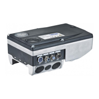
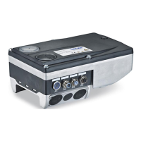
Product description
Connections and interfaces
On delivery, the PROFIBUS connections and the LEDs for the PROFIBUS status displays
are already mounted and wired:
– PROFIBUS input to plug connector X31
– PROFIBUS output to plug connector X32
– LEDs to plug connector X55
It is also possible to connect the PROFIBUS and other inputs and outputs (e.g. digital
inputs) via the positions A1 ... A4 and B1 ... B4.
For the connections, 5-pin M12 connectors or - alternatively - cable glands (cable cross-
section max. 1.0 mm
2
, AWG 18) can be used.
The M12 connectors, cable glands and prefabricated system cables can be obtained
from diverse manufacturers.
Wire the M12 connectors or cable glands used to the corresponding contacts of the
terminal strips/plug connectors X3, X4 and X61.
Hardware manual "Inverter Drives 8400 motec"
Observe the notes and wiring instructions given in the documentation.
 Loading...