Function library
Function blocks
3.5.31 Delay elements (DIGDEL)
3−183
l
EDSVS9332P−EXT DE 2.0
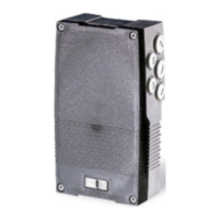
3.5.31.1 On−delay
If the on−delay is set, a signal change from LOW to HIGH at the input DIGDELx−IN is passed on to
the DIGDELx−OUT output after the delay time set under C0721 or C0726 has elapsed.
t
t
DIGDEL1−IN
DIGDEL1−OUT
C0721 C0721
Fig. 3−132 On−delay (DIGDEL1)
In this function, the time element operates like a retriggerable monoflop:
l A LOW−HIGH edge at the input DIGDELx−IN starts the time element.
l If the delay time set under C0721 or C0726 has elapsed, the output DIGDELx−OUT is set to
HIGH.
l The time element is reset and the output DIGDELx−OUT is set to LOW with a HIGH−LOW edge
at the input DIGDELx−IN.
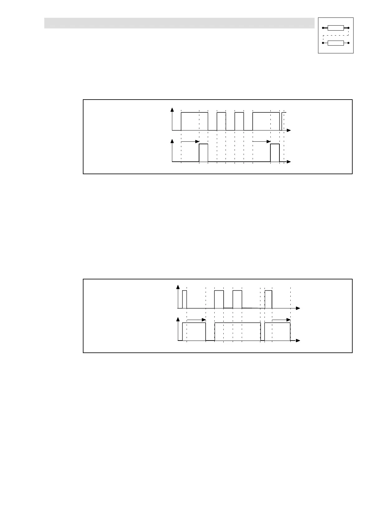
3.5.31.2 Off−delay
An off−delay causes a signal change from HIGH to LOW at the input DIGDELx−IN to be passed on
to the output DIGDELx−OUT after the delay time set under C0721 or C0726 has elapsed.
t
t
DIGDEL1−IN
DIGDEL1−OUT
C0721 C0721
Fig. 3−133 Off−delay (DIGDEL1)
l
A LOW−HIGH edge at the input DIGDELx−IN causes the output DIGDELx−OUT to be set to
HIGH and the time element to be reset.
l The time element is started with a HIGH−LOW edge at the input DIGDELx−IN.
l After the delay time set under C0721 or C0726 has elapsed, the output DIGDELx−OUT is set to
LOW.