Printhead assembly adjustment
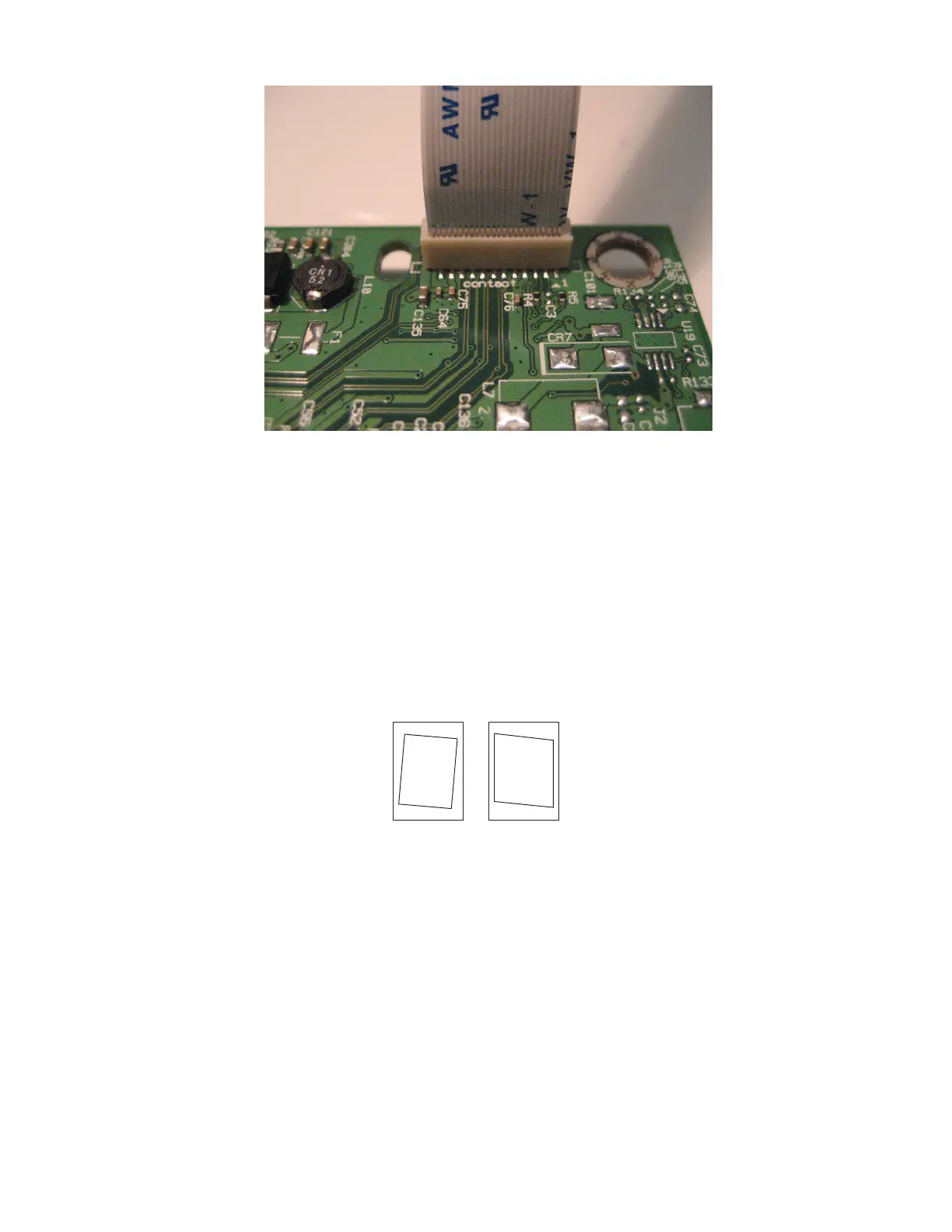
A printhead must be correctly positioned after it has been removed. Use a sharp pencil or a small, flat-blade
screwdriver to mark the location of the old printhead on the printer frame. Align the new printhead relative to
the location of the old printhead.
Note: Skew is caused by a sheet being fed through the printer while misaligned. The entire image is rotated
relative to the sheet edges. However, a mechanically misaligned printhead causes the horizontal lines to
appear skewed, while the vertical lines remain parallel to the vertical edges. The skew cannot be adjusted.
Check the pick tires for wear, the paper path for obstructions, the fuser for proper setting, and the tray paper
guides for proper setting.
Paper feed
skew
Printhead
misalignment
To adjust the printhead:
1 POR into the Diagnostics menu, and print a Quick test page:
Diagnostics Menu > Print Tests > Tray 1 > Single
2 Fold the printed test page on the left side so that a few millimeters of grid lines wrap around the outside of
the fold.
4600-830, -835, -895
Parts removal
175
 Loading...