Manitowoc Published 12-05-17, Control # 032-23 3-71
18000 OPERATOR MANUAL OPERATING CONTROLS AND PROCEDURES
HYDRAULIC SYSTEM CALIBRATION
PROCEDURES
General
To ensure proper operation of the crane functions, the
following items must be calibrated or tested at the intervals
specified in this folio:
• Pressure Senders
• Controls (pump centers)
• Pump Pressure
• Charge Pressure
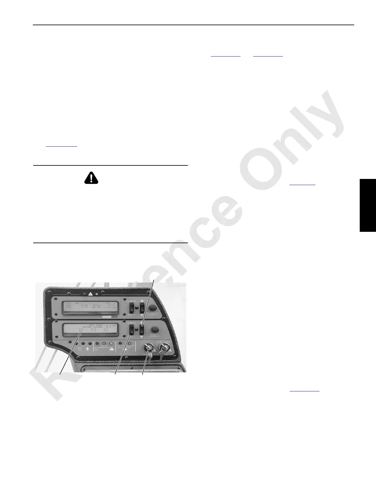
See Figure 3-47
for identification of the controls used for
calibration and testing.
Pressure Sender Calibration
See Figure 3-47 and Figure 3-48 for the following procedure.
The pressure sender line of the calibration screen indicates if
each system’s pressure sender null (0) is within 0.65-1.35
volts.
The pressure senders must be calibrated at the following
intervals:
• When a new controller node is installed
• When a pump is replaced
• When a pump control (EDC or PCP) is replaced
• When a pressure sender is replaced
• When displayed pressure is not correct
Be aware that if there is any residual pressure in the
system during the calibration process, the display
pressure reading in the cab may not reflect actual
system pressure. See Note on page 3-71
.
• Every 6 months
To perform pressure sender calibration, proceed as follows:
1. Stop engine and turn ignition switch to RUN position.
2. Access calibration screen shown below as follows:
a. Select and confirm SETUP mode to activate
calibration program.
b. Turn LIMIT BYPASS switch clockwise and hold.
c. SCROLL UP at least one screen.
d. Continue to scroll up or down until calibration screen
appears.
e. Press bottom of CRANE MODE switch until (*)
appears next to PRESSURE SENDER CAL.
f. Then press top end of CRANE MODE switch to
CONFIRM. Calibration will start.
g. When calibration starts, percent (%) of completion is
displayed on screen.
h. When calibration stops, check bank 1 and bank 2
binary numbers:
- If 0 appears, all pressure senders have passed
calibration.
- If any number other than 0 appears in either
bank, use the table in Figure 3-48
to determine
which senders have failed calibration.
- Each pressure sender is assigned a number in
the binary system (power of two). After running
the calibration procedure, outputs that are ON
(failed) for any sender, are added together. To
identify the failed senders, find the binary
WARNING
Moving Load Hazard!
With engine running, crane functions (drums, boom hoist,
swing, travel) can operate unexpectedly while system
components are being calibrated or tested.
To prevent crane functions from moving, turn PARK ON
for all crane functions before you perform calibration or
testing procedures.
P1744
Digital
Display
Screen
Scroll
Up-Down
Rocker
FIGURE 3-47
Crane
Mode
Switch
Limit Bypass
Switch

 Loading...


